Get in Touch with Koven Air Company

Water-Source Heat Pump Commissioning, Controls & Troubleshooting Guide


Updated: October 13, 2026
A water-source heat pump is a reversible refrigeration unit that exchanges heat with a circulating water loop. That defines the unit. Loop operation requires a heat sink or source. There needs to be sufficient flow of the circulating water at each unit, and a control sequence needs to be developed. People need to own the resulting records.
This document follows how the system operates from design inputs through handover, focusing on duties that broader HVAC systems and a stand-alone cooling system cannot resolve at the terminal unit alone. This guide is written for owners, consultants, facilities teams, contractors, and technical buyers who need to define responsibilities and acceptance evidence. Product scope, capacity, configurations, price, lead times, quotes, and RFQ intent stay on Koven Air’s commercial water-source heat pump solutions page. For a broader technology comparison, use the industrial and commercial heat pump guide.
Quick scope
- Three boundaries: occupied space, refrigerant circuit, and water/source loop
- Six project inputs: Load, Ventilation, Source Range, Hydraulics, Water Quality, Controls
- Proof chain: design basis, field verification, baseline, trend record, and corrective-action proof
- For the commercial handoff, model selection and purchasing remain on the solution page
Key takeaway
A rated heat-pump unit is only one part of a WSHP system: a water-source heat pump contains a compressor, refrigerant circuit, and heat exchangers, while the loop and plant provide the external source and sink duties. Define the source, loop, ventilation, controls, acceptance measurements, and operating owner before final equipment selection.
What a Water-Source Heat Pump Commissioning Boundary Must Separate
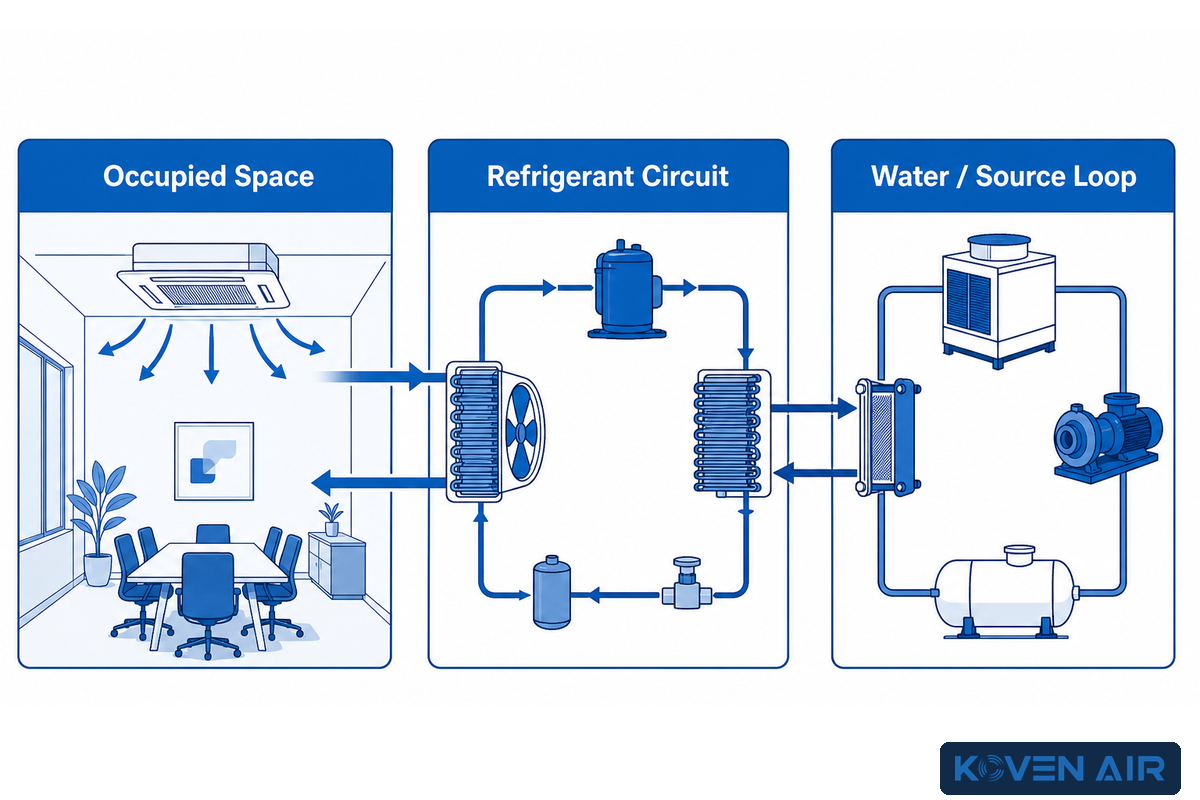
For commissioning and troubleshooting, treat loop water as the heat-transfer path rather than the external source or sink; the records should distinguish heat transferred at the water-side exchanger from heat added by external sources or rejected to external sinks beyond the building loop. In cooling mode, the refrigerant absorbs heat from the air at the indoor coil before the water-side exchanger moves that load into the loop; outside air remains a separate ventilation duty. The compressor uses electrical work to compress refrigerant; the water side then transfers the heat to loop water via a heat exchanger, with that water serving as the heat exchange medium. During heating, the reversing valve changes the refrigerant path so the unit takes heat from the water loop and delivers it indoors.
The word source can be misleading. Circulating water is the heat exchange medium for thermal energy transfer through the building, not an endless energy supply; evaluate its transport duty separately from system performance and energy use. The loop relies on an external source to provide energy or an external sink to reject it. A boiler-and-tower system adds heat when the water in the loop becomes too cool, and rejects heat when it becomes too warm. Closed loop systems include closed-loop ground fields that exchange net heat with the earth through sealed piping. An open loop WSHP can use groundwater, subject to local codes and regulations.
In cooling, a water source heat pump system uses its refrigerant cycle and heat exchangers to transfer heat from the building to loop water; the direction reverses in heating, and the loop remains an exchange medium rather than the building’s underlying energy source. The external plant, ground, groundwater, or surface water arrangement closes that energy path.
For system ownership, the terms water-source, water-loop and geothermal are interrelated but not synonymous. The US Department of Energy’s geothermal purchasing guidance describes ground-coupled and groundwater configurations, but a commercial water loop heat pump system with a boiler and cooling tower isn’t a geothermal system. A water to water heat pump is different. In this case the load side serves water, e.g. a hydronic heating circuit.
The useful system boundary has three parts:
- Occupied-space boundary: Loads, air flow, filtration, ventilation, humidity, condensate, sound, and comfort.
- Refrigerant boundary: compressor, reversing valve, expansion device, coils, safeties, and model-specific controls.
- Water/source boundary: Flow, temperature, pressure, pumps, strainers, valves, water quality, central heat addition or rejection, and the external source.
Problems cross those boundaries. A high-pressure trip could indicate a refrigerant fault. Poor water flow or inadequate heat rejection could also produce the trip. A local thermostat reading does not prove that the system can cool the space under design load, and it says little about pump energy, tower operation, or whether ventilation is handled elsewhere. Keeping those boundaries identifiable prevents one contractor from being charged for failing to address evidence that belongs to another.
How a Water-Source Heat Pump Transfers Heat Across System Boundaries
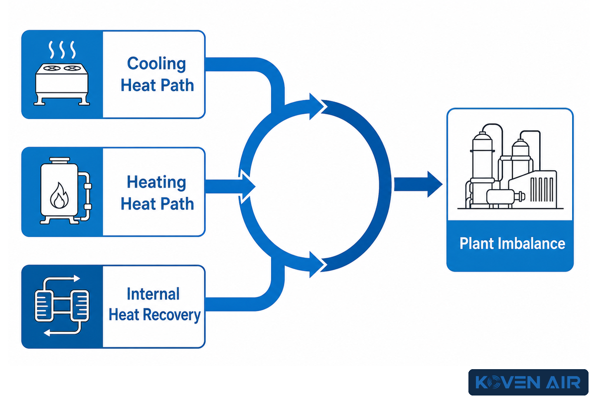
Within the unit, the refrigerant cycle and compressor do the lifting, while heat exchangers transfer thermal energy across the air, refrigerant, and water boundaries. During cooling, the air coil carries heat from the air to the refrigerant circuit before the water-side exchanger transfers it to the loop. During heating, thermal energy transfer follows the reverse path, and useful heat is absorbed from water in the loop. Compressor work joins the heat stream in either case, so heat pumps use electrical input to absorb or reject heat; useful heat absorbed from water at one boundary is not identical to heat rejected at another.
A two-pipe shared loop can simultaneously serve heating and cooling zones. Cooling units on the loop reject heat and heating units on the loop take up heat. When there’s an overlap of loads, the heat of the building can be redistributed internally. The central plant handles the imbalance. That’s useful heat recovery; however, it doesn’t make the building self-sufficient. The loop still requires an external energy source or sink when the zones don’t balance, as well as pumps and controls.
The discussion of water-source systems in Trane engineering illustrates loop heat sharing, pumping, and balancing strategies as well as reset controls. Those examples illustrate typical design conditions, not absolute design constraints. For project-specific limits, the selected unit manual and the project’s design calculations generally describe the actual operating envelope.
One modeled office-building example in that source examined a loop range from 60°F (16°C) to 90°F (32°C). The table below reports its normalized annual HVAC energy results; it’s evidence about the effect of combined strategies in that model, not a temperature prescription or a forecast for another building.
| Modeled climate | Base WSHP | Optimized WSHP | Rounded WSHP reduction | Optimized GSHP | Rounded GSHP reduction |
|---|---|---|---|---|---|
| Atlanta | 100% | 78.5% | about 20% | 61.5% | about 37% |
| Louisville | 100% | 83.5% | about 15% | 58.5% | about 40% |
| Minneapolis | 100% | 89.5% | about 8% | 74.5% | about 24% |
Read the modeled performance and energy results separately: the optimized WSHP columns retain 78.5%, 83.5%, and 89.5% of normalized base energy, while the optimized GSHP columns retain 61.5%, 58.5%, and 74.5%. Trane summarizes the modeled reductions as about 20%, 15%, and 8% for the optimized water-source system and 37%, 40%, and 24% for the ground-source case. The spread reinforces the point: climate, building use, outdoor-air delivery, pumping, optimal start, and loop-temperature control change the result together. No single percentage proves system performance or belongs on an equipment schedule without a project model.
It’s important to understand the context of performance claims. AHRI’s WSHP certification program provides comparable ratings at stated conditions. Even so, the model does not certify the building’s pump selection, loop balance, tower controls, well performance, or maintenance record. Product ratings and installed system proofs are answers to different questions.
Define the Loop Architecture Before Final Unit Selection

Water-source heat pump systems can use several loop architectures, and the choice clarifies responsibilities that a unit schedule can’t address. It determines where net heat will be transferred, what heat transfer fluid contacts the equipment, how the unit connects to the central plant, who owns water treatment, and what permits and/or environmental constraints may apply. The final selection should be made after these have been named.
| Loop/source type | External source or sink | Main project questions | Acceptance evidence |
|---|---|---|---|
| Open cooling tower + boiler | Evaporative heat rejection and central heat addition | Reset, staging, tower water program, freeze strategy, pump control | Sequence test, balanced flows, plant proof, water-program records |
| Closed-circuit cooler + boiler | Indirect evaporative rejection and central heat addition | Fluid boundary, spray-water program, coil approach, winter operation | Both circuits verified, sequence test, treatment and freeze records |
| Dry cooler + boiler | Sensible outdoor-air rejection and central heat addition | Climate extremes, fan control, footprint, sound, peak rejection | Design-condition review, fan staging, flow and backup proof |
| Vertical closed ground loop | Borefield exchanges heat with the ground | Ground model, bore layout, grout, fluid, purge, long-term drift | Bore log, pressure test, purge and fluid records, thermal baseline |
| Horizontal closed ground loop | Trenched piping exchanges heat with shallow ground | Available land, soil and moisture, trench layout, disturbance, purge | As-built layout, pressure test, backfill, purge and baseline |
| Open groundwater discharge | Groundwater is withdrawn and discharged to an approved destination | Sustainable flow, chemistry, drawdown, discharge route, permits | Pump test, analysis, approval and seasonal source baseline |
| Open groundwater reinjection | Groundwater is returned through an injection well | Injection pressure, interference, chemistry, fouling, well approvals | Source/injection tests, analysis, approvals and pressure baseline |
| Surface-water closed coil | A submerged closed circuit exchanges heat with a pond or lake | Seasonal temperature, anchoring, access, materials, environmental review | Source survey, coil inspection, pressure test and baseline |
| Hybrid or auxiliary source | Ground, water, process or ambient source plus auxiliary plant | Mode priority, changeover, failure response, metering, ownership | Mode-change test, backup proof, trends and source accounting |
The US Department of Energy’s geothermal purchasing guidance identifies peak load, temperature of the ambient groundwater, flow rate of the well, and quality of the groundwater as project inputs. They are feasibility conditions, not submittal details that can be determined at a later date. For an open loop, the authority having jurisdiction may also regulate withdrawal, discharge, reinjection, or well construction. Confirm the path you’re taking rather than adopting a permit rule from a different area.
A cooling tower adds another operating program. The CDC states that both open- and closed-circuit towers should be managed for scale and corrosion, sediment, and cleaning and disinfecting. “Closed circuit” describes one fluid boundary; it does not remove the tower’s aerosol, basin, treatment, and recordkeeping responsibilities.
Use the 6-Input Design-Lock Framework Before Selection
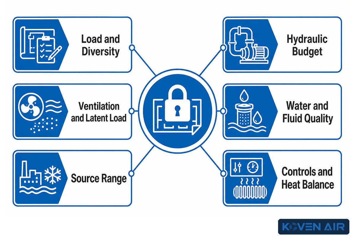
The Six-Input Design Lock is a project register, not an industry standard. Its purpose is to prevent a model comparison from being performed while the duty remains ambiguous. Each input must have a source, owner, design value or schedule, verification method, and a hold point.
| Input | Record before final selection | Typical hidden assumption |
|---|---|---|
| Load and diversity | Zone loads, schedules, simultaneous heating/cooling profile, and design conditions | Installed capacity is treated as measured demand |
| Ventilation and latent load | Outdoor-air path, humidity target, air-side equipment, condensate and control owner | Terminal heat pumps are assumed to solve all fresh-air duties |
| Source range | Expected entering-water range by season and mode, plus external plant limits | One catalog test point is treated as the annual condition |
| Hydraulic budget | Design flow, pressure losses, pump head, diversity, balance method, and permitted valve states | The pump curve is accepted without the system curve |
| Water and fluid quality | Chemistry, materials, filtration, inhibitor or antifreeze plan, sampling and treatment owner | Clear water is treated as compatible water |
| Controls and heat balance | Sensor list, reset logic, pump proof, boiler/tower staging, alarms, fail states, and trend points | Zone thermostats are assumed to coordinate the central loop |
Don’t average conflicting documents. Identify the applicable design condition, trace the values to their source, and resolve discrepancies with the respective designers and equipment data. The final equipment schedule should show which input revision was used. This will result in a clean change path when the well test, tower selection, ventilation load, or piping calculations change later.
Exact values for water temperature, flow, pressure drop, fluid concentration and chemistry, etc., pertain to the equipment and design of the project. For projects that obtain heat from water sources, the DOE purchasing guidance treats peak load, source temperature, well flow and groundwater quality as project inputs rather than universal defaults. An example of a value shown in an engineering example may aid in illustrating a relationship; however, this shouldn’t be copied to other locations without consideration of the assumptions made for that example.
Control the Loop, Not Just the Thermostat
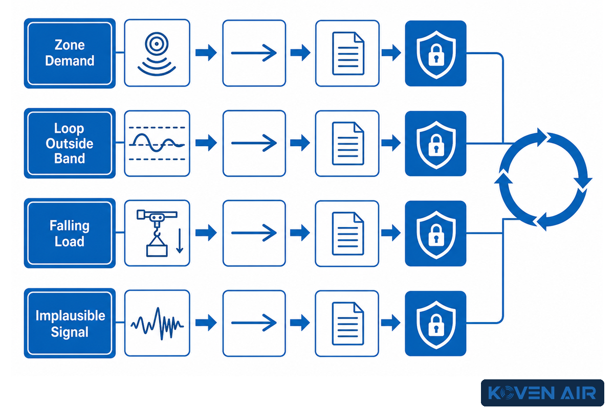
A zone thermostat can request heating or cooling, but it can’t prove that the common loop can support the request. The sequence of control should integrate terminal units, distribution pumps and valves, central heat addition and/or rejection, alarms and other relevant control functions. The key control question isn’t “what should be controlled”, but “what sensor indicates that each of the prerequisites is achieved”?
| Observed condition | Control action | Proof to retain | Failure response |
|---|---|---|---|
| Zone demand appears | Open path and request circulation | Command, valve state, pump status, and flow proof | Hold compressor and identify the missing proof |
| Loop moves outside its project band | Stage heat addition or rejection per sequence | Sensor trend, plant command, response time, and as-left state | Alarm before terminal limits are reached |
| Load falls while pumps run | Reset flow or pressure within the approved strategy | Remote differential pressure, active valve position, and pump speed | Protect minimum unit flow and investigate unstable hunting |
| Signal becomes implausible | Enter the documented fallback mode | Alarm, substituted value, affected equipment, and operator response | Avoid silent operation on a failed sensor |
Loop reset can reduce unnecessary central heat addition or rejection, and variable-flow pumping can reduce distribution energy. Both depend on sensor placement, valve behavior, minimum flow, and a stable control hierarchy. A control strategy that’s modeled to save energy may not be possible in the field if a remote branch doesn’t receive adequate differential pressure or if terminal units and controls fight the central control loop.
State the sequence in plain language prior to programming. Document what initiates the transition, the action, proof, time allowance, alarm, fallback, and recovery for each. The PNNL ground-source heat-pump O&M resource is a useful independent reference for the loop, pumping and control responsibilities that sit outside the room thermostat. That will prove more beneficial during commissioning than a simple list of point names.
Commission the Loop First, Then Prove Each Unit

Whole-project commissioning begins before installation, with owner requirements, design review, submittals, and responsibility assignments. It continues throughout the construction process, and after occupancy during operation. This guide’s field layer of the commissioning process, the Four-Stage Commissioning Pack, is presented in the next section. The Four-Stage Commissioning Pack isn’t a replacement of a full-commissioning process, and isn’t endorsed as an industry best practice.
- Prove loop readiness — close flushing and cleaning records, remove air, inspect strainers, verify fluid and water results, confirm valve line-up, balance branches, and record pump duty.
- Complete unit pre-start — verify water piping routed to the unit, flow direction, isolation, drains, condensate, filters, power, controls, safeties, sensor identity, and the approved model data.
- Test modes and controls — demonstrate heating, cooling, pump proof, valve response, central plant enable, alarms, fallback states, and recovery under stated conditions.
- Freeze the baseline — retain entering and leaving water temperatures, verified flow or pressure-drop evidence, electrical data, air conditions, setpoints, alarms, defects, owners, and as-left status.
Testing terminal units depends on water, and therefore the water system is tested first. Starting units before flushing and balance are closed can distribute debris, hide trapped air, and produce data that cannot be compared later. The ClimateMaster engineering handbook discusses high-point venting, system strainers, drains, isolation, condensate pitch, balancing, and water-side measurements. Those are transferable, and the model and example values remain within their context.
A checkbox isn’t acceptance evidence. The ENERGY STAR HVAC commissioning checklist reinforces the need to verify installed systems and document commissioning results. “Pump running” requires proof of the operating state, and a flow or pressure measurement. “Unit cools” requires proof that the unit cools the air and can cool the space under stated air and water conditions, electrical input, control command, and active limits; it also requires confirmation that the water piping routed to the unit is ready. “Alarm tested” should show the initiating condition, annunciation, fallback, reset rule, and recovery.
The baseline will be useful in the future only if it can be replicated by other technicians. Record instrument identity or calibration status, date and time, mode, active zones, central plant state, fluid condition, unresolved deviations, and any other relevant conditions. Assign ownership to each open item and don’t change the acceptance band width after the test.
Build a Maintenance Record That Can Diagnose Drift
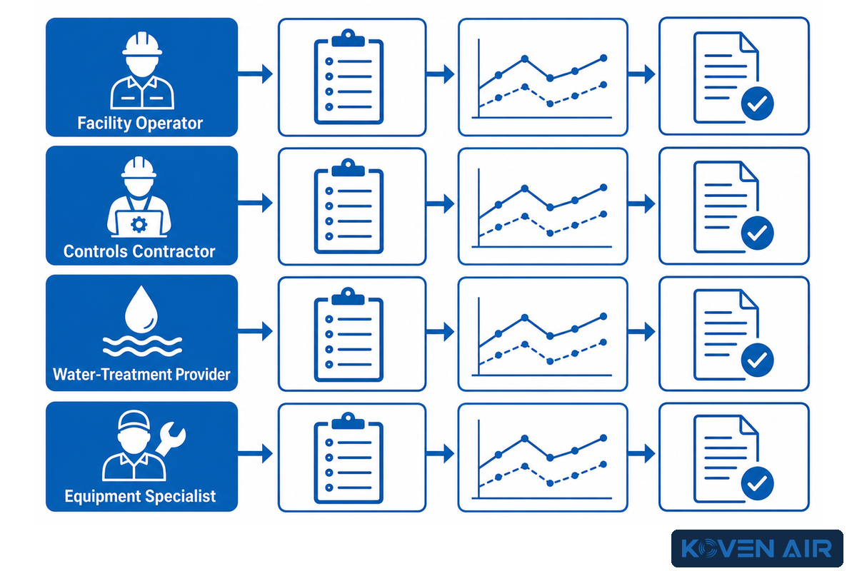
Maintenance has two jobs: preserve equipment condition and make deterioration visible early enough to act. A calendar can help schedule work, but it cannot show changes in equipment condition, system performance, flow, water quality, sensor drift, or control-sequence stability. Both measurements and outcomes should be recorded.
PNNL’s ground-source heat-pump O&M guidance (PNNL source) lists useful operating records such as temperatures, electrical current, well flow, injection pressure, water level, and water quality. Some fields apply only to ground or open-loop systems, but the method is broader: record the measurements that describe the actual source and heat-transfer path, then compare them with the commissioning baseline and manufacturer data.
| Owner | Records to maintain | Escalation trigger |
|---|---|---|
| Facility operator | Modes, temperatures, alarms, comfort calls, pump/tower/boiler status, resets and operating context | Repeated alarm, widening deviation, unstable control, or unexplained energy change |
| Controls contractor | Sensor checks, sequences, overrides, trend configuration, alarm routing, firmware and change history | Persistent override, implausible signal, hunting, or loss of proof |
| Water-treatment provider | Sample results, treatment, corrosion/scale indicators, blowdown, cleaning and corrective action | Out-of-band result, rapid consumption, deposit, corrosion, biofilm, or unstable control |
| Equipment specialist | Flow/pressure evidence, air and water temperatures, electrical readings, heat exchangers, filters, condensate, refrigerant diagnosis and as-left test | Model-specific limit, unresolved performance loss, repeated lockout, or intrusive repair need |
Where a cooling tower is present, the site water-management program owns its health controls. CDC’s cooling-tower module covers scale and corrosion, sediment, and cleaning; disinfectant residual and monitoring, and records. This obligation exceeds that of a heat pump maintenance visit.
Each corrective action should be completed with evidence. A strainer that has been cleaned should be recorded as closed with the post-cleaning condition and operating measurement. A replaced sensor needs to be recorded as closed with a comparison or calibration. A chemical treatment should be recorded closed with a post-test measurement. Without a second measurement, the record shows activity, not recovery.
Check Water-Side Causes Before Changing Refrigerant Charge
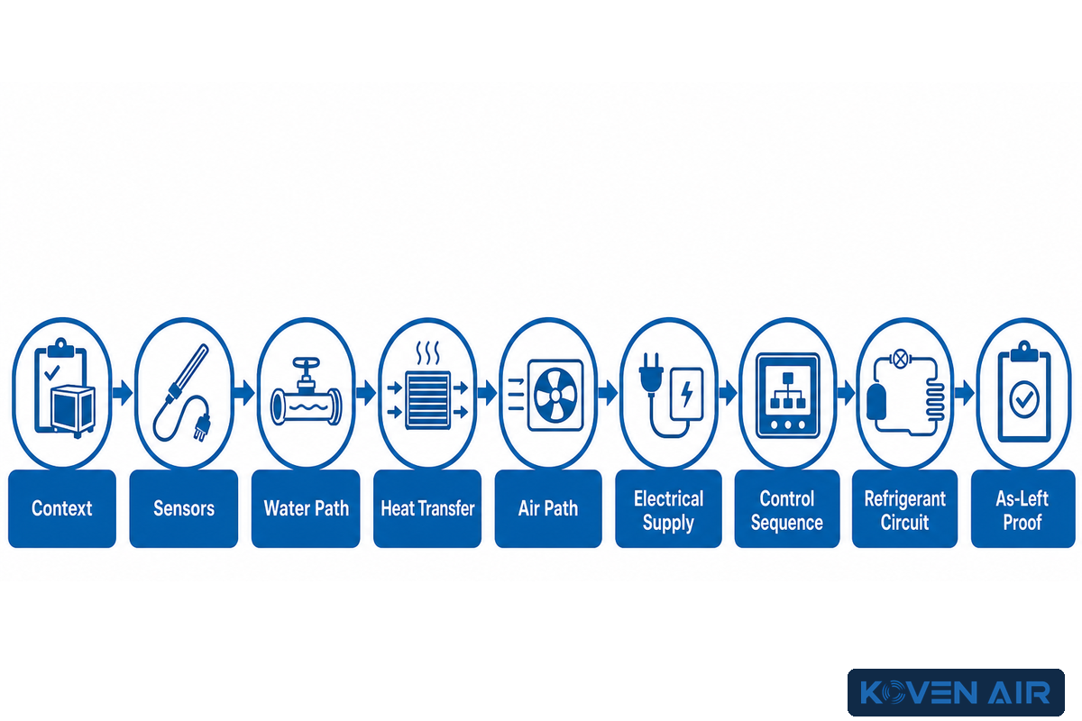
This diagnostic order relies on conditional evidence, not intuitive judgment. This order should be performed only when symptoms suggest heat transfer, pressure or repeated lockout. It does not claim that every WSHP fault begins in the loop. Start with the operating context and fault history, then test the least intrusive boundaries before altering a sealed refrigeration circuit.
| Step | Question | Evidence | Next branch |
|---|---|---|---|
| Context | Which mode, load, zones and central-plant state produced the symptom? | Alarm time, commands, loop trend, outdoor/source condition, recent changes | Reproduce only under an approved test plan |
| Sensors | Are the temperatures, pressures, flow proof and valve states believable? | Independent check, signal range, point mapping, calibration history | Correct bad evidence before diagnosing hardware |
| Water path | Is design flow reaching the unit without blockage, air or mispositioned valves? | Pump and valve state, strainer condition, pressure drop or verified flow, air and balance evidence | Compare with baseline and approved equipment data |
| Heat transfer | Do air and water changes make sense for the active mode and load? | Entering/leaving water, return/supply air, electrical input, coil/heat-exchanger condition | Separate air, water, control and refrigeration possibilities |
| Air path | Are filter, fan, coil, duct and condensate conditions consistent with the symptom? | Airflow evidence, filter and coil condition, fan command, drain inspection | Correct the air-side restriction or drainage fault and retest |
| Electrical supply | Are supply, protection, connections and current consistent with the manual? | Approved electrical measurements, protection state, connection inspection | Isolate and correct the electrical cause before repeated starts |
| Control sequence | Did commands, proofs, safeties and fallback states occur in the intended order? | Point trend, sequence, override history, alarm and reset evidence | Repair the evidence or sequence before condemning hardware |
| Refrigerant circuit | After other boundaries are proved, what does the sealed circuit show? | Model-defined test conditions, approved instruments and qualified diagnosis | Follow the exact service procedure; do not infer charge from one symptom |
| As-left proof | Did the corrective action restore stable operation under the stated condition? | Before/after readings, operating context, alarms, owner and follow-up date | Escalate or keep the issue open if recovery is not demonstrated |
An accessible Heating Help field discussion shows the importance of this order. A high-head case was initially framed as possible overcharge, while replies challenged the assumption with water-flow, debris, and entering/leaving water checks. That is practitioner evidence, not a design standard, and the exact temperature preference in the thread should not be generalized.
Do
- Preserve the fault context before resetting
- Validate sensors and water flow with measurements
- Compare current readings with the commissioning baseline
- Use the exact model’s service procedure
Don’t
- Treat one alarm as a root-cause label
- Assume new piping contains no debris
- Change refrigerant charge from one symptom
- Bypass safeties to keep a unit running
Intrusive service stops at the site’s competent-person boundary. OSHA’s hazardous-energy guidance requires applicable energy-control procedures and trained workers during service and maintenance. Refrigerant, electrical, pressurized-water, and chemical tasks also follow the equipment manual and local requirements. Repeated trips should be investigated, not defeated.
Decide Whether the System Fits the Building

WSHP systems are good candidates when different zone loads are present, when a practical route for water distribution exists, when an external source or sink is feasible, and when an operation team exists that can operate the controls and maintain water quality records. The DOE feasibility guidance is a useful cross-check for source temperature, flow, water quality and site constraints. It becomes a poor fit when the source is assumed, ventilation has no owner, the loop cannot be balanced or maintained, local water constraints are unresolved, or responsibility ends at the terminal-unit connection.
| Fit question | Proceed when | Pause when |
|---|---|---|
| Do zones create useful heat diversity? | Load profiles show meaningful simultaneous heating and cooling or other system value | Diversity is a sales assumption with no load record |
| Is the source loop feasible? | Source range, hydraulics, water quality, space and permits are resolved | A well, tower, boiler, ground field or rejection path remains undefined |
| Are air-side duties assigned? | Ventilation, latent load, filtration, condensate and acoustic targets have owners | Fresh air and humidity are expected to solve themselves |
| Can the site operate the evidence chain? | Controls, water treatment, trends, alarms and service responsibilities are funded and assigned | No one owns baseline records or repeated alarms |
Use this scorecard to decide whether the system concept is ready for engineering development. Once the boundaries and duty are defined, the water-source heat pump solution page can address product-specific selection, capacities, configurations and inquiry. The industrial and commercial heat pump hub shows the adjacent equipment families. If the load side is a hydronic water circuit rather than room air, compare the boundaries with the air to water heat pump guide before finalizing the system type.
Document the fit decision as a short project minute. Identify the preferred architecture and state the reasons for rejecting the alternatives. Identify any unresolved conditions. Name the owner of the evidence. State the event that will close each hold point. This prevents a provisional design intent from remaining an assumption until it becomes a permanent design fact. It also defines a clean boundary for procurement. The team can compare compliant equipment without asking vendors to guess the well condition, tower duty, outdoor-air load, or control intent.
A no-fit decision can be valuable. It may indicate that the building requires a dedicated outdoor air system, a different heat rejection path, a hydraulic separation strategy, more plant space, or a site team able to manage water treatment. Close that system gap prior to picking a terminal unit. If the architecture later evolves, run the six-input register instead of carrying the previous selection over.
Have the six project inputs ready?
Send Koven Air the load profile, ventilation duty, source-water range, hydraulics, water quality and the control sequence for a project-specific equipment discussion.
Koven Air is a manufacturer of industrial and commercial HVAC equipment with in-house engineering and testing. To learn more about the plant, process and support boundaries, go to the Koven Air company page.
Frequently Asked Questions
What Should a Water-Source Heat Pump Commissioning Record Contain?
To document how water source heat pumps work in the installed system, the commissioning package should identify each unit as a reversible refrigeration device that exchanges heat with a circulating water loop. It should record entering and leaving water conditions in cooling and heating. It should prove the loop and unit control sequence. It should also identify the external heat source and sink, approved baseline, open items, and record owner.
Does Every Water-Source Heat Pump Commissioning Plan Need Cooling-Tower Proof?
The commissioning record should identify whether a boiler-and-tower system, a closed ground loop, or an open-loop groundwater source handles net heat rejection. When a cooling tower or fluid cooler is used, the commissioning record should prove its sequence. It should also record ground-loop limits or groundwater conditions. Because the architecture changes pumping, water treatment, permitting, controls and maintenance, each proof needs an owner. “No tower” still requires source-loop engineering evidence.
Is a Water-Source Heat Pump Water-Quality Plan Specific to the Source?
The water-quality owner should record whether the water-source application uses a closed ground loop, suitable groundwater, or a commercial boiler-and-tower loop. The record should distinguish ground-source and geothermal arrangements from a heat pump whose heat source and heat sink are mechanical. It should also state the approved chemistry, test method, limits, corrective action, and responsible party.
How Is a Water-Source Heat Pump Control Test Different from a Water-to-Water Test?
The control test should prove how water-source terminal units condition air on the load side and exchange heat with water on the source side. For water-to-water terminal units, it should instead prove the hydronic heating, chilled water, process water, or domestic hot water interface on the load side, where the heating or cooling process serves water instead of room air. Test distribution, safeties, setpoints, resets, enable signals, alarms, and control ownership before handover.
What Should Be Checked and Frozen Before Selecting a WSHP?
Record the load and diversity, ventilation and latent-load strategy, expected source-water range, design flow and pressure budget, water or fluid quality, and the control and heat-balance sequence. Each item has an owner and a means for verification. A model comparison is done after the project inputs are stable.
What Should Be Checked Before Changing Refrigerant Charge After High Head Pressure in a Water-Source Heat Pump?
A high-head-pressure trip is a protective response to an unsafe or out-of-range condition, not a root-cause code. Refer to the mode and model for specific options, e.g. insufficient water or air flow, misplaced valve, clogged strainer, fouled heat exchanger, high incoming water temperature, trouble with control or sensor, or refrigeration fault. Preserve the recorded operating context, stop or isolate the unit as its model-specific instructions require, and follow those instructions before changing the charge.
How Should a Water-Source Heat Pump Maintenance Interval Be Set and Verified?
Combine equipment manuals, operating hours, site conditions, water quality, alarms, history, filter and condensate condition, and the building’s water management program. Operator observations, trend reviews, seasonal inspections, and annual proof records serve different evidence windows. A calendar will not tell you if a loop or unit is drifting.
Can AHRI Ratings Predict Performance, or Must the Building Verify It?
Products can be compared at stated test conditions based on AHRI ratings. However, loads, source temperatures, pumping, heat addition and/or rejection, ventilation and controls, part load operation, installation and maintenance affect a building’s performance. AHRI ratings can be used to support a product claim, but the performance of the installed system should be validated through performance tests.
References & Sources
- US Department of Energy, Purchasing Energy-Efficient Geothermal Heat Pumps
- AHRI, Geothermal Water-Source Heat Pumps Certification Program
- Pacific Northwest National Laboratory, Ground-Source Heat Pump O&M Best Practices
- CDC, Controlling Legionella in Cooling Towers
- OSHA, Control of Hazardous Energy
Final review
Before release, confirm that the source loop, air-side duties, model limits, controls, acceptance measurements, water-management program, maintenance ownership, and escalation path are all written down. A complete unit submittal can’t fill a missing system boundary.
Factory Selection Support
Turn this guide into a usable HVAC RFQ package.
Share design conditions, airflow, temperature, humidity, process load, room use, and scope boundary. Koven Air can recommend a practical equipment route before quotation.
7equipment families
ISO / GMPcleanroom review
RFQscope comparison
What to prepare before quote
- Use settingCommercial building, cleanroom, hospital, data center, process area, or retrofit.
- Operating conditionsAirflow, load, temperature, humidity, static pressure, and duty hours.
- ConstraintsFootprint, access, hygiene class, material, controls, documentation, and delivery boundary.
Final equipment selection depends on local codes, project drawings, and confirmed site conditions.