Get in Touch with Koven Air Company

Industrial & Commercial Heat Pumps: A Practical Systems Guide

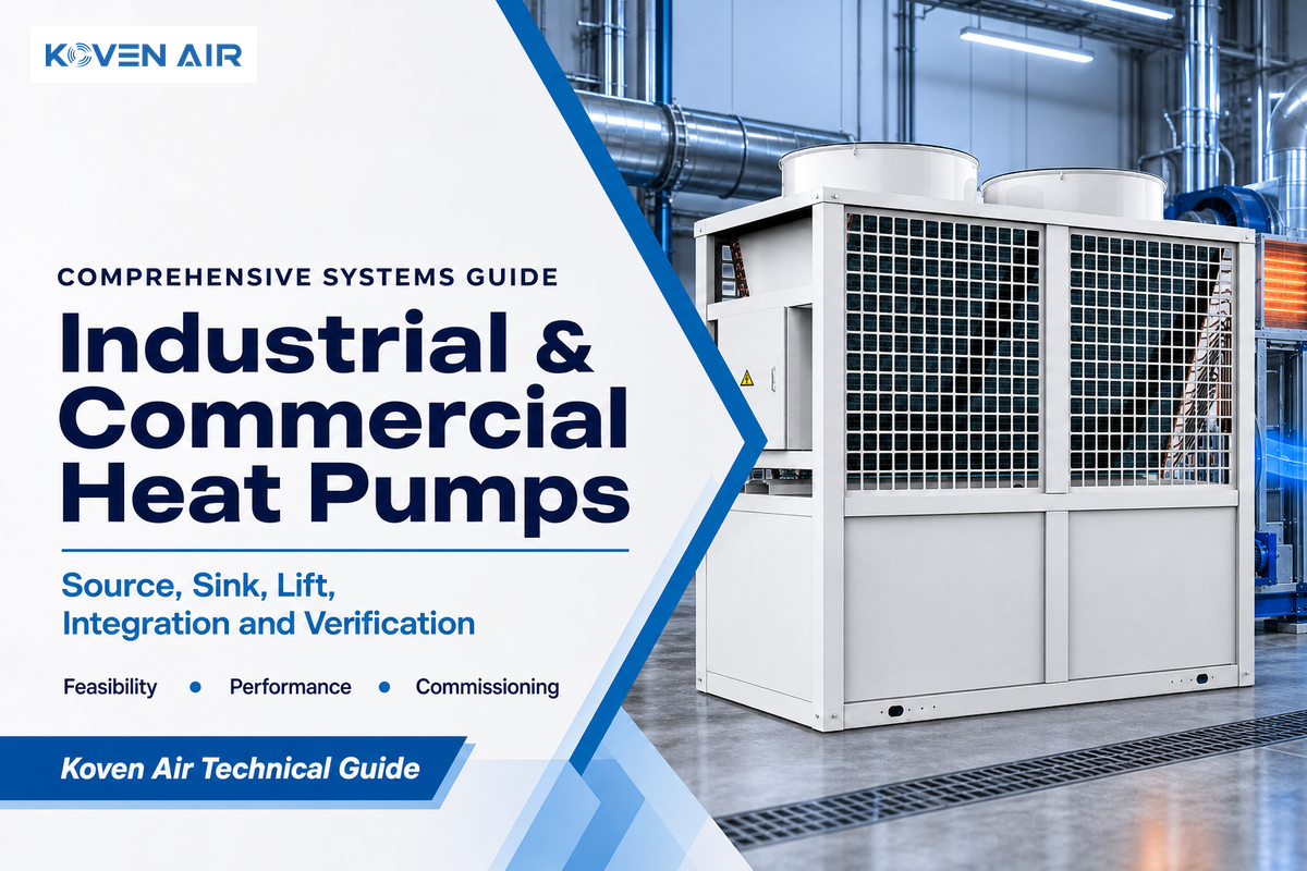
Industrial & Commercial Heat Pumps are systems that move useful heat from a lower-temperature source to a higher-temperature sink by adding mechanical work. That definition is simple. Dependable project design isn’t. Building schedules, process temperatures, source availability and distribution, controls, electrical capacity, and commissioning all impact the result. This guide explains the engineering decisions that shape a dependable project. It does not compare equipment models, capacities, refrigerants, quotations, or lead times. Those commercial questions belong on Koven Air’s heat pump solutions page, so the two pages serve different search intents.
The short version
Start with three facts: the temperature and availability of the heat source, the temperature required by the load, and the load profile over time. Then compare performance at those conditions, design the surrounding system, and verify the result with measured commissioning data.
What Industrial and Commercial Heat Pumps Actually Do
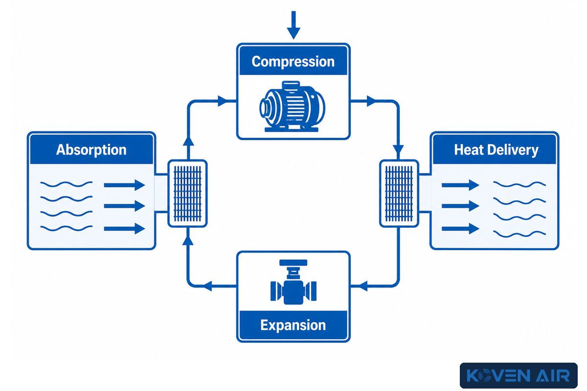
Heat pumps capture heat and move it from a lower temperature level to a higher temperature level using mechanical work. In a system, a compressor raises the pressure and temperature of a refrigerant so that heat can be released at that state. The IEA Heat Pumping Technologies Programme describes this as work being used to transfer heat from a lower level to a higher level.
How does an industrial heat pump work?
- Absorption: the refrigerant in the evaporator absorbs heat from the process source and changes state.
- Compression: a compressor adds work to the refrigerant, increasing its pressure and temperature.
- Heat delivery: the condenser transfers heat to the sink.
- Expansion: a pressure-reducing device prepares the refrigerant to change state and absorb heat in the evaporator.
Both building and process systems contain thermodynamic loops. The duty that surrounds them is different. For example, a packaged rooftop unit may serve conditioned spaces, while a hydronic system may serve a warehouse, offices, or a domestic hot water system. In an industrial setting, an installation may recover heat from a refrigeration system or supply hot water for washing or drying processes elsewhere in the facility. In some facilities, heating and cooling occur simultaneously, and in that case, heat rejected from one duty becomes the source for another.
Each heat pump is a component in a larger thermal system. The source of heat must be available. The sink must be able to accept the flow and temperature. The system must be made up of functioning pumps, fans, valves, storage, emitters, and controls. The electrical system and backup facilities must also support the system. Calling the equipment HVAC does not define those interfaces, and nominal capacity alone does not prove that the complete system can meet the load.
Commercial Buildings and Industrial Process Heat Are Different Duties
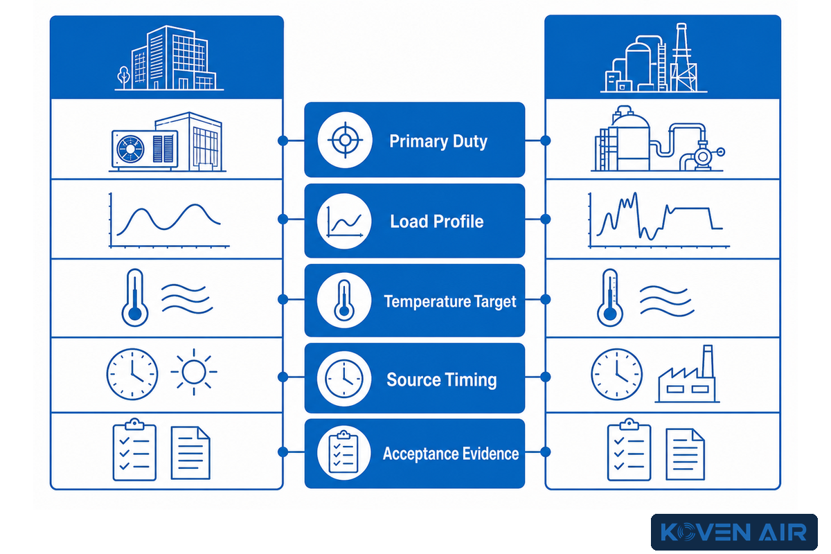
Building systems generally serve people and building functions, i.e., space conditioning, ventilation, and domestic hot water. Industrial systems serve the function of producing the product and often support building services. They typically involve timing for batch processes, sanitation, and recoverable heat that only exists while another process is occurring. Often, systems that support building and process functions are lumped together and a comparison is made for a “heat pump load.” Information needed for a sound comparison is often omitted.
| Decision point | Commercial building | Industrial process |
|---|---|---|
| Primary duty | Comfort, ventilation, reheat, or service hot water | Process water, drying, washing, evaporation, or recovered heat |
| Load profile | Weather, occupancy, ventilation, and schedules | Production batches, shifts, recipes, cleaning cycles, and uptime |
| Temperature target | Set by terminals, air systems, or domestic-water requirements | Set by product and process requirements, sometimes with tight tolerances |
| Source opportunity | Outdoor air, ground, water loop, exhaust, or heat recovery | Cooling plant, wastewater, exhaust, product cooling, or adjacent process |
| Critical constraint | Comfort, humidity, ventilation, acoustics, and peak weather | Production continuity, contamination control, redundancy, and process quality |
| Source timing | Outdoor or loop conditions vary with weather and building schedules | Waste-heat availability varies with production, cleaning, and shutdowns |
| Failure consequence | Comfort, service interruption, freeze protection, or tenant complaints | Lost production, product quality, safety, or an interrupted batch |
| Acceptance evidence | Zone conditions, schedules, airflow or water flow, input, and backup operation | Process temperatures, thermal flow, input, product limits, and recovery duty |
This classification should happen prior to equipment comparison. For instance, a building may have a short winter peak, but spend the rest of the time at part load. Process duty may remain steady while the waste-heat source varies with production. Refrigeration plants may appear to provide “free heat,” but useful heat and demand may not coincide. Thermal storage or backup may resolve some mismatches, but should be sized with time-based data instead of an annual energy total. For commercial heating, the HVAC system boundary should include distribution and ventilation if they materially affect energy efficiency, energy bills, and energy costs.
The distinction changes economic analysis. Commercial buildings may value comfort, avoided boiler operation, and cooling-system replacement. An industrial project may value the simultaneous avoidance of heating and cooling, process stability, lower fuel use and energy recovery. Neither case can be judged from catalog efficiency alone, because what commercial heat pumps cost to operate depends on the actual duty, tariff, and system boundary.
Use the Source–Sink–Lift Triangle Before Comparing Equipment
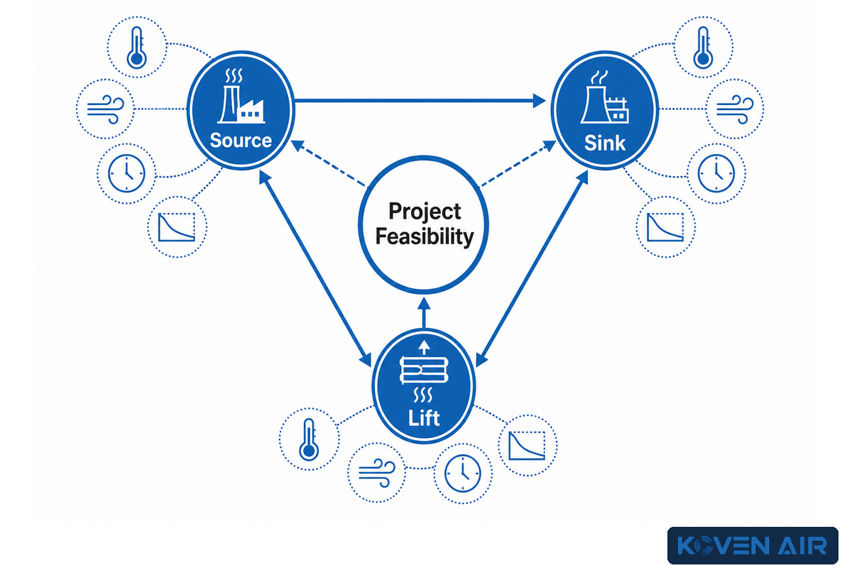
The Source–Sink–Lift Triangle is a three-part feasibility screen:
- Source: What heat is available, at what temperature, flow, and with what level of cleanliness? Where is it located, and when is it available?
- Sink: What temperature, flow, and control tolerance does the heat load require? What’s the availability?
- Lift: How much does the system need to raise temperature to meet the design load? What about under off-design conditions?
Temperature lift is the difference between the conditions of the source and the sink. The larger the temperature lift, the less efficient the equipment and the harder the compressor works. This is why a COP, or coefficient of performance, published at mild source and sink conditions can’t be applied to a high temperature lift project without a performance map. Refrigerant, compression technology, staging, approach temperatures, auxiliaries, and part-load control all affect performance.
| Input | Minimum evidence to record | Common blind spot |
|---|---|---|
| Source | Entering/leaving temperature, flow, hours, fouling, freezing or corrosion risk | Using an annual average that hides the worst operating hour |
| Sink | Required supply/return temperature, load duration, ramp rate, allowable interruption | Assuming the legacy boiler setpoint is the minimum useful temperature |
| Lift | Matched source/sink pairs across the operating envelope | Comparing one headline COP instead of the actual temperature map |
The triangle often shows a better first move. It is often easier to reduce temperature lift by lowering a hydronic supply temperature, increasing heat-exchanger area, or recovering a warmer waste-heat source before selecting a unit. In practice, it is easier to separate a high-temperature step from a large low-temperature step than to force the whole large lift through one high-temperature stage.
A 2025 IEA HPT article identifies very large temperature lifts in heavy industry as a major challenge. It also describes one project-specific two-stage architecture, which is useful as an example rather than a universal design rule. Thresholds and performance curves may belong to that specific architecture and may not be universal. It’s always prudent to review real operating source and sink conditions, including start-up and upset conditions, and request supporting evidence from the parties involved.
How to Read COP, Seasonal, and Part-Load Ratings
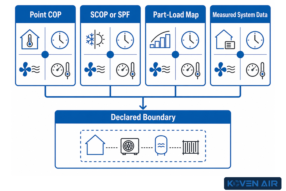
The coefficient of performance (COP) is the ratio of heat delivered (useful) to work input. A COP of 3 at a defined point means three units of useful heat are delivered for one unit of input under that boundary. This doesn’t mean that 3 units of heat are delivered for every unit of work input at every operating condition. The IEA HPT efficiency guide makes a distinction between point and seasonal COP, e.g. SCOP and SPF, and states that the system boundary defines which components are within the system.
| Metric or evidence | Useful for | Check before comparison |
|---|---|---|
| Point COP | Performance at one source/sink and load condition | Temperatures, load fraction, test method, and included auxiliaries |
| SCOP or SPF | Performance over a defined season or monitoring period | Climate/load assumptions, period, boundary, backup, pumps, fans, and defrost |
| Part-load map | Modulation, cycling, and efficiency across typical hours | Minimum stable output, control sequence, staging, and storage |
| Measured system data | Verifying installed thermal output and electrical input | Sensor accuracy, synchronized intervals, and a clearly drawn system boundary |
US regulations also illustrate why equipment class and method matter. 10 CFR §431.96 assigns different metrics and test appendices to different commercial equipment classes. That doesn’t make US procedures universal, but it does show that an efficiency number is inseparable from its scope.
Does a higher COP always mean lower operating cost?
No. There are numerous other cost factors such as the cost of energy, demand charges, fuel costs, load shape, source temperature, sink temperature, defrost, auxiliary equipment, backup heat, and controls. Comparing the economics of two units at different operating conditions is not valid. Build an energy model from matched operating points and hours, and state which pumps, fans, towers, storage losses, or backup systems are within the boundary.
For existing facilities, measured interval data is better than assumptions. Of the many variables to consider, some important ones are trending source and sink temperatures, thermal flow, and compressor and auxiliary inputs, valve positions, staging, and backup operation. Sound business cases model weather, production levels, tariffs, and time spent outside the preferred operating envelope.
System Families: A Map, Not a Model Selector
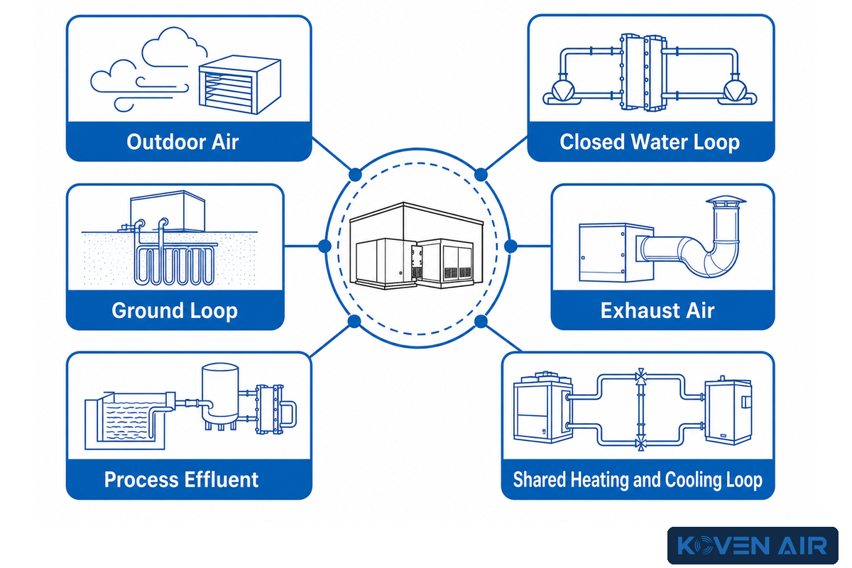
The designation of a heat pump unit reflects the location where the heat is collected or where it’s delivered. It doesn’t specify the model of the heat pump. An air-source unit has a changing outdoor heat source, may require defrost, and needs a performance map for extremely cold conditions. Water-source units may use several liquid sources and bring pump, water-quality, and permitting requirements. Ground-source systems depend on a borefield or ground-loop design. A heat-recovery or process unit can use a warmer source, but that heat must be available when required.
| Source category | Good first question | Evidence still required |
|---|---|---|
| Outdoor air | What happens at design outdoor temperature and during defrost? | Capacity map in kW, source temperature in °C, hydronic temperatures, storage, backup |
| Closed water loop | Is the loop energy balance stable across all connected loads? | Flow in L/s, pressure drop in kPa, pumps, heat rejection/addition, controls |
| Groundwater or surface water | Is the source legally available and chemically compatible? | Permits, seasonal °C range, water quality, fouling, discharge and pumping |
| Ground loop | Can the ground system balance annual extraction and rejection? | Site investigation, bore depth in m, loop design, pumping, seasonal response |
| Exhaust air | Is exhaust available whenever the heating load exists? | Airflow in m³/h, contamination, frost risk, fan power, ventilation balance |
| Refrigeration condenser | How closely do cooling rejection and useful heating demand coincide? | Hourly kWh profiles, rejection fallback, storage, head-pressure interaction |
| Process effluent | Does temperature and flow remain usable through every batch? | Minimum flow, °C profile, solids, corrosion, cleanability, exchanger approach |
| Product or process cooling | Can both thermal duties be controlled without harming production? | Batch duration in min, quality limits, simultaneous load, bypass and redundancy |
| Shared heating/cooling loop | How many hours have simultaneous useful heating and cooling? | Coincident kW loads, loop temperatures, bypass/rejection strategy, controls |
The delivery side is as critical as the source side. There are differences in how air-to-air, air-to-water, and water-to-water systems interact with ducts, hydronic terminals, process heat exchangers and domestic water storage. “High temperature” also needs to have its condition stated. Supply temperature alone doesn’t state anything about the source, lift, capacity, or stable operating range.
Building-side search labels are not interchangeable. An air-to-air heat pump can provide air-to-air heat through a split-system or packaged rooftop unit, whereas air-to-water heat pumps serve heating systems through a hydronic loop, fan coil, or AHU. In commercial properties—from light commercial spaces to large commercial and industrial facilities—air conditioning, ventilation, indoor air quality, air quality, climate control, central air, RTUs, and the outdoor unit describe different interfaces. A commercial HVAC or professional HVAC label still does not establish temperature control, reliable heating, reliable heating and cooling, or acceptable indoor conditions.
Energy claims require the same discipline. Energy-efficient or high-efficiency heat language does not prove lower energy consumption or a smaller carbon footprint. To say a design will reduce energy, use less energy, limit greenhouse gas emissions, or deliver efficient heating and cooling with consistent performance, define the baseline, operating hours, smart controls, and included HVAC equipment. SEER may describe seasonal cooling under a test procedure, but it does not establish efficient operation for a process duty.
Equipment categories also need context. Air source heat pumps, an air conditioner, or evaporator and condenser descriptions do not by themselves establish efficient heating for larger facilities. The HVAC industry may group heating and cooling systems, boilers and chillers, and other HVAC solutions together, but the engineering brief must still define the source, sink, lift, load, and acceptance evidence.
Use the taxonomy to reduce the engineering questions. Use the commercial solutions page to find product configurations, capacities, available refrigerants, models, prices, quotes, and lead times. This guide won’t assist in product buying decisions.
Integration Decides Whether the System Delivers
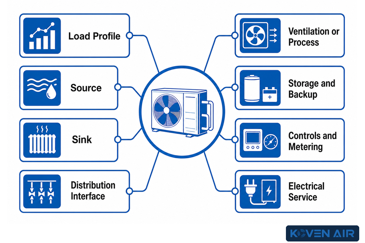
Design isn’t complete after unit selection. The “8-Input Integration Brief” provides the owner, mechanical engineer, process team, controls contractor, electrical engineer, and supplier one final opportunity to integrate their interests. It should be completed before a final unit selection is requested.
8-Input Integration Brief
- Load profile: hourly or representative heating/cooling demand and loads, peaks, schedules, growth.
- Source: Temperature, Flow, Availability, Quality, Location, and Coincidence with the Load.
- Sink: supply/return temperatures, useful capacity, ramp rate, tolerance and critical hours.
- Distribution interface:
Ducts, pipes, heat exchangers, terminals, pressure drop, pumps, and fans.
- Ventilation or process interaction: Outdoor air, humidity, exhaust, product conditions and sanitation, and contamination controls.
- Storage and Backup: buffer volume, peak strategy, redundancy, failure mode, restart requirements.
- Controls and metering: sequences, setpoints, staging, alarms, sensors, trend intervals, and system boundary.
- ELECTRICAL SERVICE: Includes voltage, capacity, demand, starting/inrush needs, harmonics, and resilience.
The brief shows that both systems are constrained by equipment and surrounding-system interfaces. Reducing supply temperature could improve heat-pump performance, but not if the terminal equipment can no longer deliver the load. Adding storage could help reduce cycling, but the benefit depends on charge conditions, losses, and the control sequence. A backup boiler can cover peak loads, but a bad staging sequence can make it operate during mild conditions and negate potential energy savings.
The PNNL commissioning guide emphasizes qualified work across load calculations, equipment selection and matching, distribution, ventilation, refrigerant charge, electrical service, controls, and documented verification. Its quantitative fault examples are residential, so this guide uses them only to support the principle of measured verification, not as commercial or industrial benchmarks. A transferable principle is measurement. This includes air or water flow, electrical input, temperature differences, control response, and delivered performance. These variables should be verified rather than assumed.
Appoint an owner for each interface. Production requirements belong to the process team; mechanical design owns air and hydraulic integration; the controls team owns the control sequence; and the electrical team verifies service and protection. The commissioning authority verifies functional outcomes. Gaps in responsibility are common system faults, even when each bought-out element is individually compliant.
Start writing the acceptance plan while the system boundary is still being defined. Initially, at least identify the source and sink conditions where capacity will be assessed, acceptable temperature and flow ranges, the electrical loads, how backup operation will be defined, and time-alignment of data. Functional tests should include normal operation, staging, defrost (if applicable), modulation, changeover, alarm and sensor failure, plus backup operation, controlled shutdown, and restart. One “unit runs” test observation can’t prove system performance.
Measurement location can affect the reported result. If measurement is taken only at the compressor input, it will exclude pumps and fans. A measurement at the plant boundary may include those auxiliaries, so the stated performance metric must identify the boundary used. Thermal meters also require proper placement, verified flow measurement, and adequate sampling to capture cycling. In general, record data at the equipment boundary if it pertains to a component, and record data at the system boundary if it pertains to the entire process. This will enable system optimizations to be performed without re-baselining the system.
Finally, define the exception process. When a test doesn’t achieve the acceptance criterion, the reason, restriction, and responsibility to correct it should be recorded. This is especially important when commissioning activities cannot challenge the design extremes. Tests that are deferred should have a clear reason and an owner assigned to perform it, not simply an agreement to “check it next winter.”
When Heat Pumps Underperform, or Are Not the First Move
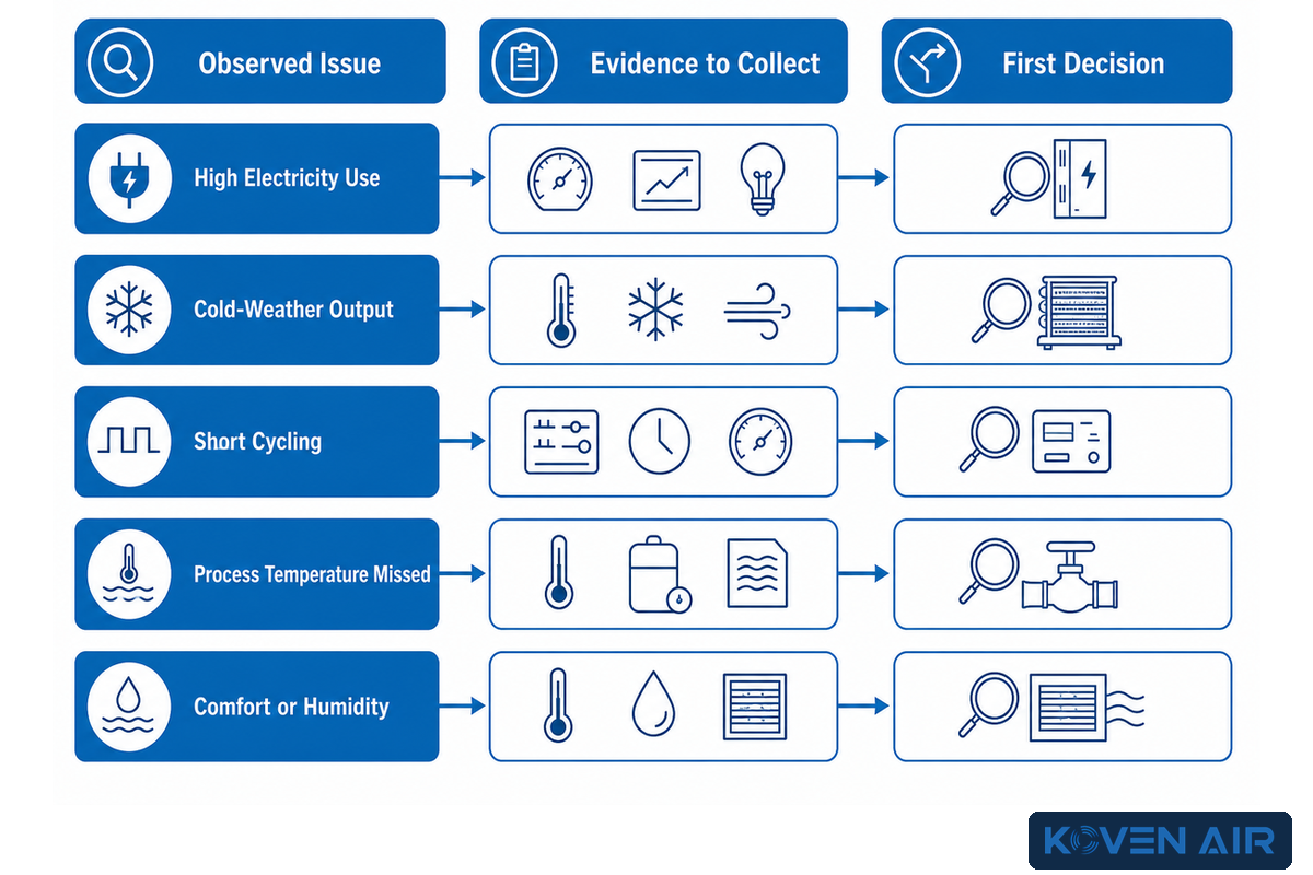
Once integration and acceptance tests are defined, heat pumps still do not “always work” or “never work.” Performance depends on duty and the overall system configuration. An adverse outcome can be attributable to limitations in the technology, but an inadequate distribution temperature, suboptimal flow, sensor issues, defrost behavior, control drift, or a backup heat condition operating unnoticed can also result in poor performance.
| Observed issue | Evidence to collect | First decision |
|---|---|---|
| High electricity use | Thermal output, compressor/auxiliary input, backup runtime, temperatures, schedules | Verify the energy boundary before blaming the unit |
| Poor output in cold weather | Outdoor condition, capacity map, defrost, coil condition, airflow, backup staging | Compare measured behavior with the design condition |
| Short cycling or unstable zones | Minimum load, minimum output, zone calls, buffer volume, setpoint deadbands | Check load match and controls before adding capacity |
| Required process temperature is missed | Source/sink conditions, flow, approach temperatures, fouling, ramp and batch timing | Confirm whether the problem is lift, interface, or timing |
| Comfort or humidity complaint | Airflow, ventilation, latent load, cycling, reheat, zone control, sensor location | Treat it as a system-control problem, not only a capacity problem |
For an air-source project in a demanding climate, the design needs to account for low-ambient conditions, defrost, drainage, wind/snow exposure, emitters, backup and controls. See the commercial cold-climate heat-pump systems page for configuration follow-up, and keep the site-specific load and commissioning basis in the engineering package.
What is the major disadvantage of a heat pump?
No single disadvantage is present in all applications. The most challenging constraint is often the temperature lift required at the critical operating hour. Other constraints may include variability in the source condition, defrost, electricity service constraints, a legacy high-temperature distribution, process uptime, and complicated control schemes. The most appropriate solution is to identify the limiting interface. A larger unit does not correct excessive temperature lift, inadequate flow, uncontrolled backup heat, or a load that exceeds the system’s design basis.
In some instances, the first project step should be an improvement to the envelope, distribution, processes, controls, or metering. These improvements may shrink the load or reduce the required temperature, making a later heat-pump installation more economical.
Repair, Recommission, Replace, or Measure Again
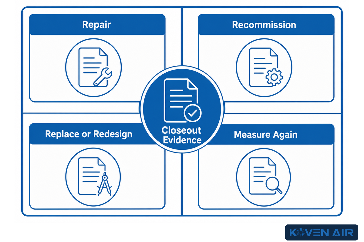
High operating cost, a comfort complaint, or a missed process target does not by itself prove that replacement is warranted. Use the 4-Path Lifecycle Matrix to decouple equipment condition from evidence quality.
| Path | Choose it when | Required closeout evidence |
|---|---|---|
| Repair | A verified component fault explains the performance gap and the remaining system is serviceable | Fault finding, corrective work, leak/safety checks as applicable, and retest |
| Recommission | Hardware can meet the duty, but flow, charge, sensors, setpoints, staging, or schedules are unverified | Functional tests, documented settings, trend data, and measured performance |
| Replace or redesign | Load/duty has changed, the unit cannot meet the verified envelope, condition is poor, or support risk is unacceptable | Updated load and temperature study, alternative evaluation, integration design, and acceptance plan |
| Measure again | The apparent problem rests on estimated loads, unsynchronized meters, or missing operating states | Corrected instrumentation, time-aligned data, stated boundaries, and a repeatable baseline |
Reworking existing equipment for a different function deserves its own procedure. Sensors can drift. Setpoints can be overridden. Schedules remain the same long after their intended use. Valves and pumps can remain in manual positions. Backup heat can stage before needed, and heat recovery can be bypassed. Functional testing can help recover equipment performance without maintaining the assumption that equipment should always be preserved.
Replacement is justified when evidence shows an irrecoverable duty mismatch or unacceptable reliability or safety risk, not simply because newer equipment has a better performance rating. Consider the load, source and sink conditions, performance maps, electrical distribution, and failure impact. Compare replacement options to the same constraints and consider lifecycle economics over the chosen planning horizon. There is no universal replacement age or service interval. Use the actual manufacturer’s operating instructions and assess site conditions, safety, and equipment integrity.
What High-Temperature Progress Means in 2026
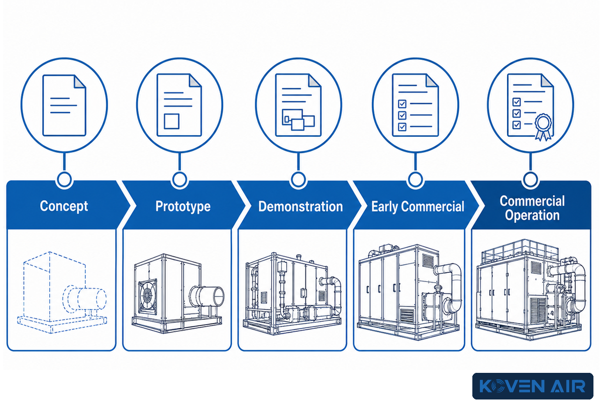
Industrial high-temperature heat pumps are developing. For some products, the stated level of readiness is in terms of temperature bands. The IEA Heat Pump Monitor 2026 reports that commercially available heat pumps could technically supply around 20% of global industrial heat demand, mainly in low- and medium-temperature processes. Technical potential is not the same as project feasibility, which still depends on site temperatures, operating hours, energy prices, integration, and capital constraints.
The same 2026 source describes heat pumps below 120°C as commercially available, systems below 160°C as beginning to enter commercial operation, and higher-temperature bands as being at demonstration, prototype, or concept stages. These are broad readiness categories, not performance guarantees for a specific project. Japan had almost 650 MW of installed industrial heat-pump capacity in 2024, equivalent to about 1% of the country’s light-industry heat demand; the geographic and sector scope of that comparison also matters.
| Readiness claim | What to request |
|---|---|
| Commercial operation at a similar temperature | Source and sink conditions, lift, capacity, hours, auxiliaries, refrigerant, and operating history |
| Early-commercial or pilot result | Project boundary, monitoring method, uptime, maintenance, scale-up assumptions, and independent evidence |
| Patent or concept | Treat it as disclosed R&D direction, not proof of certification, adoption, field reliability, or product availability |
For instance, WO2025006307A3 discloses a supercritical-CO2 architecture for high-temperature heat delivery. A patent disclosure demonstrates an arrangement; it doesn’t prove a commercial product or demonstrate suitability for a project. The appropriate question isn’t “What maximum temperature has been disclosed in a patent?” The relevant questions are “What source and sink are we addressing? What temperature lift, load, and operating hours apply?”
Decisions related to refrigerants require a current, sector-specific review. The US EPA states that from January 1, 2025 certain technologies may no longer use specified high-global-warming-potential HFCs or blends, with restrictions varying by sector and transition date. Those restrictions vary by sector and transition date. Don’t generalize and create one rule for refrigerants. Identify jurisdiction, equipment sector, project date, safety classification, code requirements, service strategy, and the rule in effect today.
From Guide to a Verifiable Project Brief
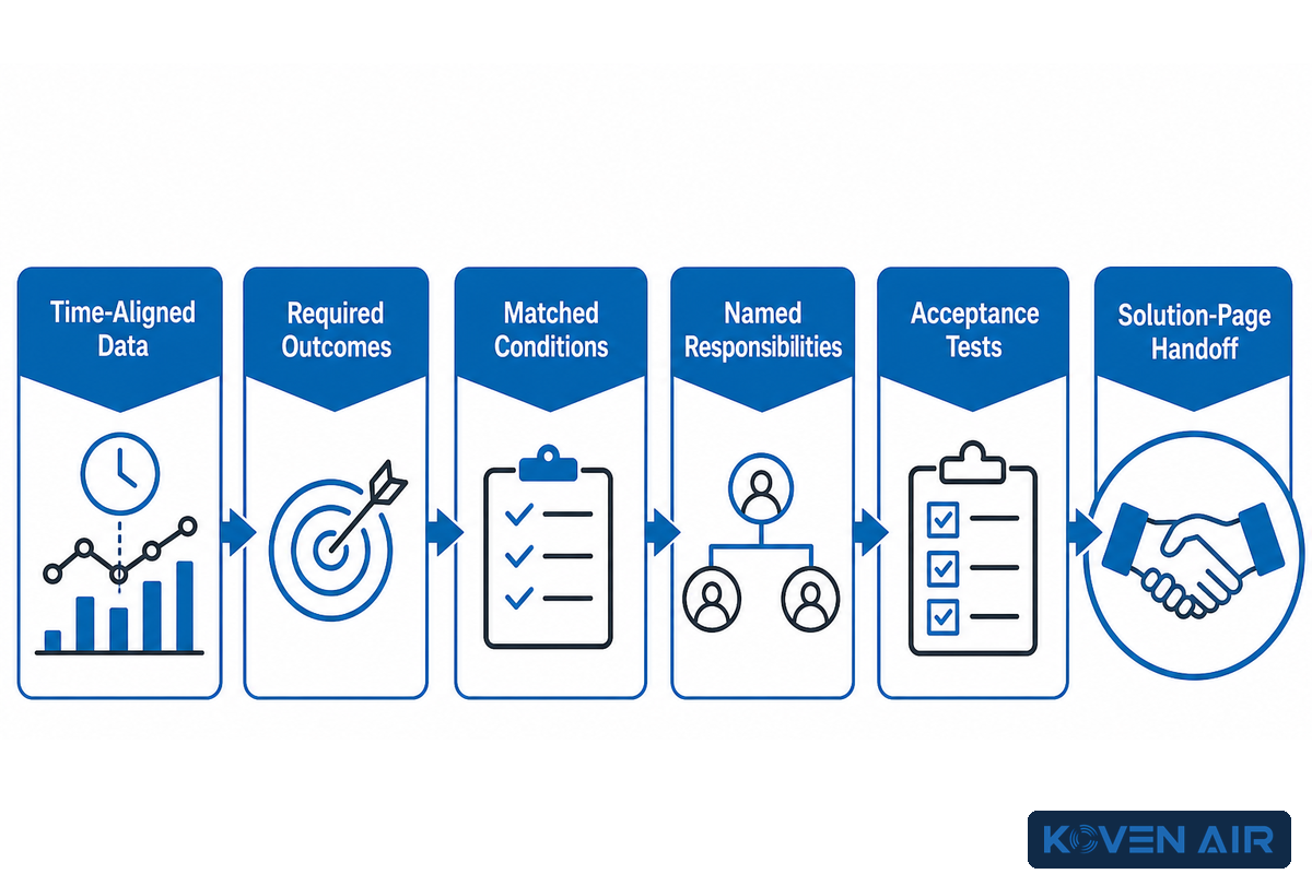
A heat-pump brief is an evidence package, not a request for the “most efficient model.” Start with the Source–Sink–Lift Triangle. The 8-Input Integration Brief and 4-Path Lifecycle Matrix then structure new-project and existing-asset decisions before anyone assumes replacement. In combination, these tools help keep product selection, feasibility, and lifecycle assessment in the right sequence.
- Time-align loads and temperatures and report the data in that fashion, rather than reporting just annual totals.
- Separate required process or comfort outcomes from legacy setpoints.
- Ensure ratings are compared under identical source, sink, load, and measurement-boundary conditions.
- Assign named responsibility for every mechanical, electrical, controls, process, and commissioning interface.
- Determine acceptance tests prior to purchase, including measurement of thermal output and auxiliary energy.
- Retain commercial configurations and RFQs on the solutions page.
For company context, review Koven Air’s company information. For a configuration discussion, bring the briefing to the solution team. Final design, codes, and acceptance criteria are engineering decisions for the project.
Discuss your heat-pump project brief
Frequently Asked Questions
Are heat pumps and HVAC the same thing?
No. HVAC describes systems that heat, ventilate, and condition buildings. A heat pump is one heat-transfer technology that can serve part of an HVAC system or an industrial process. A complete installation also needs distribution, controls, electrical service, ventilation coordination, and sometimes storage or backup. The distinction matters because good equipment can’t compensate for an incomplete system design.
How does an industrial heat pump work?
It absorbs heat at a lower useful temperature, raises refrigerant pressure and temperature through compression, and releases heat at the required sink. The cycle resembles building heat-pump operation, but industrial feasibility depends on process temperatures, source continuity, temperature lift, uptime, and heat-recovery opportunities. Performance must therefore be evaluated at the intended source and sink conditions, including start-up and off-design operation.
What is the main disadvantage of a heat pump?
There’s no single disadvantage in every application. Common constraints include large temperature lift, variable source conditions, defrost, electrical-service limits, legacy high-temperature distribution, and control complexity. Identify the limiting interface before changing technology or adding capacity. Load reduction or a lower distribution temperature may improve the project more than selecting a larger unit.
Can a commercial heat pump replace a boiler directly?
Sometimes, but not as a universal drop-in replacement. Peak load, supply and return temperatures, terminal equipment, schedules, electrical capacity, controls, and backup philosophy affect feasibility. A lower-temperature distribution system or staged hybrid design can change the answer. Review the load duration curve, not only the historical boiler size; measure actual return temperatures; check terminal output at the proposed water temperature; and define which plant serves rare peaks, outages, or defrost. The appropriate arrangement can be all-electric, staged, hybrid, or a redesigned distribution system, depending on site evidence.
Does a higher COP always mean lower operating cost?
No. COP belongs to stated test conditions and may exclude pumps, fans, defrost, backup heat, and other auxiliaries. Tariffs, load shape, source and sink temperatures, and controls also affect cost. Compare matched performance maps or seasonal evidence.
References & Sources
- IEA heat pumping Technologies: What Is a Heat Pump?
- IEA HPT: Industrial Heat Recovery with heat pumps
- IEA HPT: Industrial heat pumps for Process heating and cooling
- IEA HPT: Efficiency of Heat Pumps
- PNNL: Heat Pump Quality Installation and Commissioning
- US eCFR 10 CFR Part 431, Subpart F
- IEA Heat Pump Monitor 2026: Key Findings
- IEA HPT Magazine: Large Temperature Lifts
- IEA HPT Magazine: Designing and Integrating Industrial heat pumps
- US EPA: Technology Transitions HFC Restrictions by Sector
Final takeawayA defensible heat-pump decision connects the real source, required sink, temperature lift, load profile, system interfaces, and acceptance evidence. The product comes after that boundary is clear—not before it.
Factory Selection Support
Turn this guide into a usable HVAC RFQ package.
Share design conditions, airflow, temperature, humidity, process load, room use, and scope boundary. Koven Air can recommend a practical equipment route before quotation.
7equipment families
ISO / GMPcleanroom review
RFQscope comparison
What to prepare before quote
- Use settingCommercial building, cleanroom, hospital, data center, process area, or retrofit.
- Operating conditionsAirflow, load, temperature, humidity, static pressure, and duty hours.
- ConstraintsFootprint, access, hygiene class, material, controls, documentation, and delivery boundary.
Final equipment selection depends on local codes, project drawings, and confirmed site conditions.
Related Posts


Trending now