
Get in Touch with Koven Air Company


![Cleanroom HVAC Systems: ISO Classes & Design Guide [2026]](https://kovenair.com/wp-content/uploads/2026/07/cleanroom-ahu-pharma-biotech-guide-featured-2.png)
Updated July 2026.
A cleanroom HVAC system is the equipment that filters, cools, dehumidifies, and pressurizes air to a specification no comfort-cooling system is ever required to meet, so that a pharmaceutical or biotech plant can hold both an ISO 14644-1 particle class and a GMP Grade at once. Get one wrong and the failure doesn’t result in a comfort complaint, it shows up as failed environmental monitoring and/or quarantined product. This guide will detail how these systems work, what the specifications say they do and don’t require, and where new GMP builders frequently miss the spec.
Quick Specs
| Air changes per hour (ISO 5-6) | 100-300 ACH, terminal HEPA |
| Air changes per hour (ISO 7-8) | 30-80 ACH |
| HEPA/ULPA filtration efficiency | HEPA ≥99.97% at 0.3 µm (US standard); ULPA ≥99.9995% at 0.12 µm |
| Positive pressure differential | 0.03-0.05 in. w.g. between adjacent grades |
| Temperature & humidity control | ±0.5-1°C / ±3-5% RH, application-dependent |
| Architecture options | Centralized ducted AHU, decentralized FFU, or DX split system |
What Is a Cleanroom HVAC System?
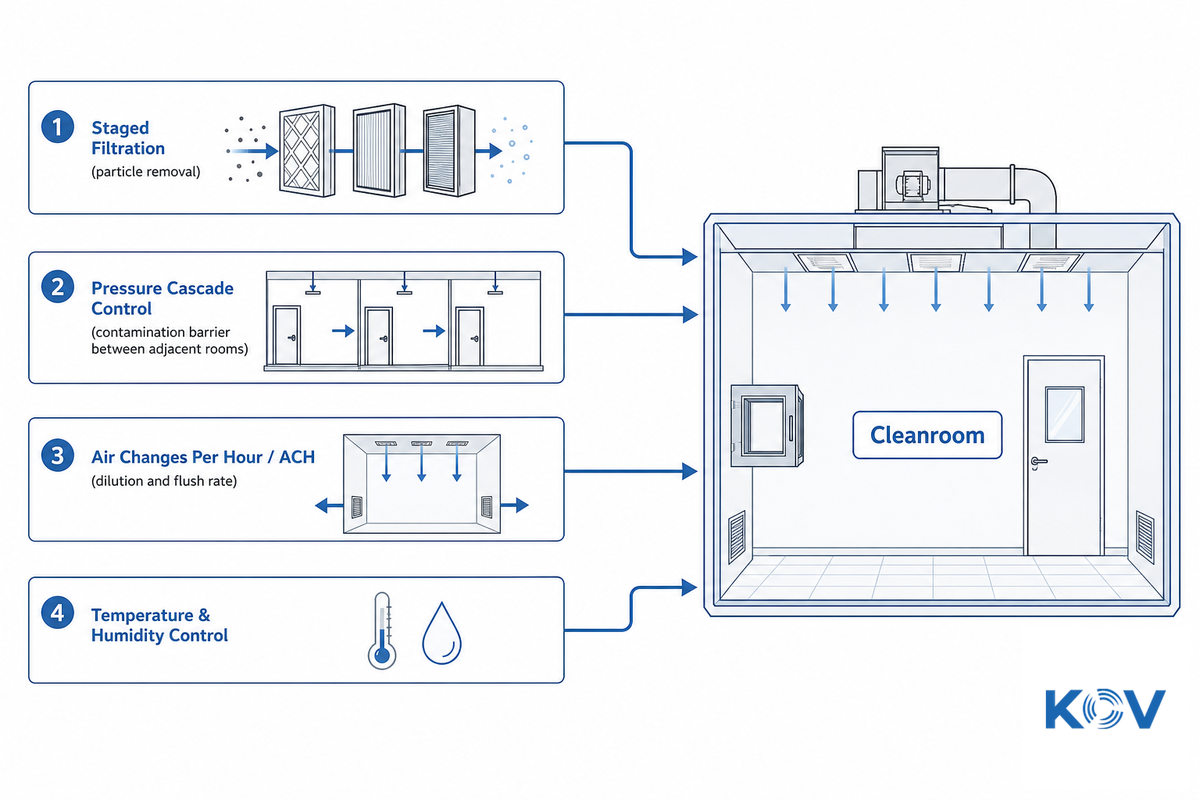
A cleanroom HVAC system does everything a normal building’s HVAC does, plus three extra jobs: it removes airborne particles through staged filtration, it holds a pressure cascade so contaminated air from next door can’t cross over, and it delivers enough air changes per hour (ACH) to flush particles the process itself generates – all in service of the classification ISO 14644-1 defines.
Underlying those three functions is a fourth, less obvious one: temperature and humidity control fine enough that a process requiring stringent parameters never detects the building’s environmental control system working at all. Call the space a clean room, a cleanroom, or a controlled production space – the underlying hvac solutions look the same whether the industry is pharma, biotech, semiconductor, or medical device manufacturing. Understanding the role of HVAC in a cleanroom space starts right here, before any specific equipment gets chosen, because the risk of getting this wrong is not a comfort complaint – it’s a failed batch. Koven Air engineers each of these four functions as a decoupled control loop rather than a single generic package, precisely because a design that treats them as one problem tends to fail at the first audit.
Distribution equipment will vary by the size and layout of a given facility. Fan filter (FFU) units, sometimes called hvac units on their own, may be installed directly into the ceiling grid and directly pump conditioned air downward; larger air handler units (AHUs) may distribute conditioned air through ducts or a plenum system; and small cleanrooms lacking a central chilled-water plant use a DX (direct expansion) split system to achieve cooling. When the goal is a properly designed clean room hvac solution, it’s important to recognize that a one-size-fits-all solution doesn’t exist-a given facility will have a certain number of filter and other necessary apparatus to serve cleanliness class and available utilities (see figure 3 below, Architecture Comparison).
A key consideration when designing the ventilation system is not only air volume but also air flow pattern. When designing a system to be capable of meeting extremely low levels of airborne particles, laminar air (unidirectional) airflow patterns are most common in the cleanest class applications (e.g. ISO Class 1 semiconductor manufacturing) with high air change rates, in which direct transfer through the contamination is superior to dilution. Where airflow patterns are more turbulent, relying on a mixing and dilution process for control, those processes generally accept that direct transfer will not be controlled. Room pressure, along with the need for makeup air (outside air) and outside air controls, must be factored in alongside airflow pattern itself.
ISO 14644-1 Classes and GMP Grades Explained
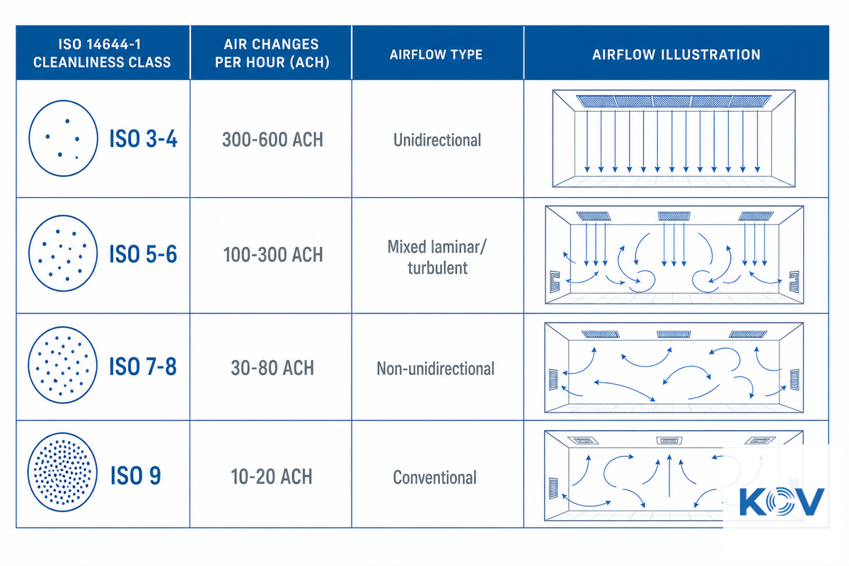
Here’s a distinction that’s glossed over in much of the vendor literature: ISO 14644-1 bases classification of cleanrooms solely on airborne particles concentrations-it doesn’t itself specify an ACH number or a HEPA ceiling-coverage percentage. These figures are post-design heuristics used by designers to meet the desired particle count reliably, not by any stretch of the word a mandate written into the standard itself. This distinction matters because it explains why you’ll see a range of ACH and coverage numbers published across vendor sites: they’re describing conventional practices, not quoting the rulebook.
| ISO Class | Typical ACH Range | Airflow Type | Typical GMP Grade |
|---|---|---|---|
| ISO 3-4 | 300-600 | Unidirectional | Grade A (semiconductor-grade) |
| ISO 5-6 | 100-300 | Mixed laminar/turbulent | Grade A/B |
| ISO 7-8 | 30-80 | Non-unidirectional | Grade C/D |
| ISO 9 | 10-20 | Conventional | Uncontrolled/support space |
⚠️ The Ceiling-Coverage Myth
A widely-cited statistic asserts that ISO 7-8 cleanrooms should use HEPA filters covering “15-25% of the ceiling.” We independently verified this figure with external sources before reproducing it, and we found discrepancy. One cleanroom design guide proposes 25-40% coverage for ISO 6 cleanrooms, while a design manual describes “close to 100%” coverage for the cleanest classes. All of these numbers aren’t technically “wrong;” they each describe an actual design solution, not a hard requirement of ISO 14644-1. Ask a vendor to cite the source for any specific coverage percentage that they present as an official standard requirement.
Why Pharma & Biotech Facilities Need a Different HVAC Approach
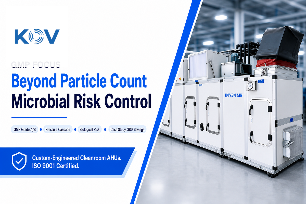
Pharma and biotech HVAC differs from semiconductor HVAC because the mapping between ISO class and GMP grade isn’t perfectly linear: a semiconductor cleanroom targets sub-micron particle count almost exclusively, while a pharma filling line must also control microbial contamination on top of that same particle target.
That extra requirement forces a system design that optimizes pressure differentials and filtration around biological risk, not just the target particle count.
To illustrate this, consider a practical example from a Koven Air GMP retrofit. The facility, a ~45,000 m² pharma plant operating with a Grade C background and Grade A/B laminar areas, was equipped with an integrated AHU (320 kW cooling / 280 kW heating). The system was configured with staged filtration: G4 → F8 → H11 followed by terminal H14 units, using gel-seal filter frames and mirror-polished 316L stainless interior surfaces rated for VHP decontamination. By converting to EC fans with variable speed drives (VFDs), the project achieved a 38% annual energy savings. Comparing this consolidated energy savings figure to external benchmarks can be tricky because publicly available data from third-party analyses often separates energy savings derived from fan speed modulation (frequently cited as 15-40%) from savings resulting from heat recovery (commonly cited as 30-50%). A real-world retrofit project, on the other hand, generates a single, blended savings figure. It’s worth asking vendors to specify whether their energy savings are based on actual measurements or on an accumulation of savings from various individual components.
Centralized AHU, Decentralized FFU, or DX Split System, Choosing Your Architecture
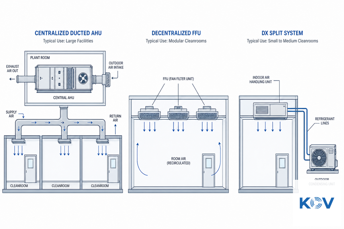
Before comparing filter grades or ACH figures, there’s an architectural decision that dictates most of what follows: will the air for the cleanroom come from a single centralized unit, or from dedicated units located within each room? Getting this wrong is a common and expensive mistake for first-time GMP builders, because retrofitting a centralized plant onto a facility built around standalone units is a structural, not a mechanical, problem. Koven Air builds all three architectures – centralized ducted AHU, decentralized FFU, and DX split – specifically because no single configuration fits every industrial buyer’s site constraints.
DX hvac systems – an indoor air handling unit and an outdoor condensing unit tied together by refrigerant lines – are the most common solution for smaller cleanrooms where a central chilled-water plant isn’t feasible or already in place. FFUs: a number of fan filter units are mounted within the ceiling grid of a room, drawing air from the room itself – modular clean room module designs patented as recently as 2024 (US20240288184A1) continue to refine this approach – and they work well in small, one-room labs but validation gets increasingly difficult and burdensome to document as a facility grows. Centralized AHUs: a single air handling unit feeds air to multiple rooms; this approach is the industry standard for full GMP facilities, where one controlled air source makes building management system integration, energy recovery, and pressure-cascade validation dramatically easier to defend during an audit.
| Architecture | Best-Fit Facility Size | Chilled-Water Plant Required? | Typical Use Case |
|---|---|---|---|
| Centralized ducted AHU | Full facility, multi-room | Yes (or dedicated central plant) | Full GMP facilities, aseptic filling suites |
| Decentralized FFU | Single small room/lab | No | QC labs, single-room ISO 7-8 spaces |
| DX split system | Small-to-mid, no central plant | No (refrigerant-based) | Retrofits, remote sites, mid-size cleanrooms |
Q: What is the difference between a Cleanroom Plenum System vs. a Direct-Ducted HVAC System?
View Answer
A plenum system employs the ceiling space above the ceiling as a large air supply reservoir to multiple terminal filter modules or FFUs from a single source; this method saves duct cost in the ceiling space in the case of rooms with numerous terminal filters. The direct-ducted method supplies individual ductwork to each filter/diffuser; although this results in increased cost for the duct material, it allows more precise control of the amount of airflow delivered to each area. For smaller rooms with only a few filters direct ducting is more economical, while for large rooms with an abundance of filters the plenum system is a better solution.
How Filtration Staging Actually Works, From Pre-Filter to Terminal HEPA/ULPA
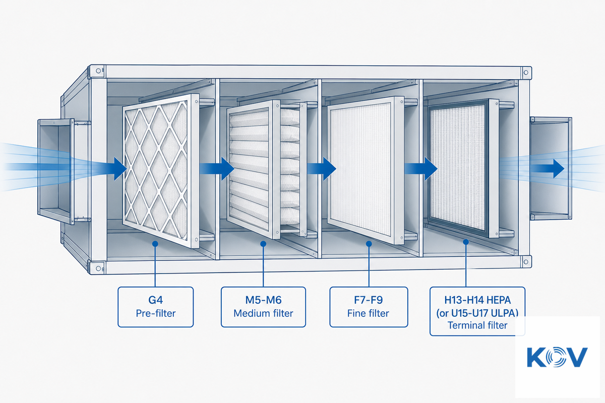
Cleanroom air doesn’t travel through one heroic filter, but instead through a staged series: G4 pre-filter → M5-M6 medium → F7-F9 fine → H13-H14 HEPA (or U15-U17 ULPA) terminal, with each stage protecting the more expensive one that follows it downstream.
Skip the medium and fine stages, and you’re asking your expensive terminal HEPA filter to absorb a particulate load it wasn’t sized for, shortening its service life – a mistake Koven Air’s engineers see often enough on retrofit projects that the full G4-through-H14 chain is specified as standard, not an optional upsell.
HEPA stands for High-Efficiency particulate air; the standard the EPA cites is a US one for a minimum 99.97% removal at 0.3 microns (the “most penetrating particle size”). That’s not exactly the same thing as the European EN 1822 H13/H14 grading, which is an efficiency measurement against whatever the most penetrating particle size is for the actual filter media, rather than a fixed 0.3-micron benchmark. (A filter could carry an H13 or H14 rating that doesn’t precisely align with 99.97%). ulpa (Ultra-Low Penetration Air) filters go up to 99.9995% at 0.12 microns, which is the air quality requirement in the cleanest semiconductor fabrication or pharma manufacturing facilities. (Actual) filter Service Life: The complication that many of the “clean room standard” articles brush under the rug is how often these filters need to be changed.
One HEPA/ULPA vendor suggests 1 to 5 years of life. A second sources cites a HEPA life of 3 to 5 years, and a ULPA life of 2 to 3 years. And yet a third estimates 5 to 8 years of life for ULPA filters.None of these answers is inherently right or wrong.
Actual service life depends heavily on what’s getting caught in the filters, the degree to which upstream stages of air cleaning are well-maintained and the frequency with which they’re being replaced as scheduled. Avoid taking a single lifespan number without further probing on what usage it assumes.
Validation & Documentation Auditors Actually Check
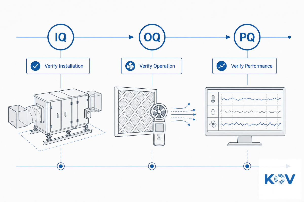
Passing an audit isn’t a matter of your particle count and pressure differential happening to fall within limits when somebody glances over the top – it’s about the record demonstrating they were as well-within-limits at 2am as they were at 2pm. That’s the reality of continuous, ALCOA+-compliant (attributable, legible, contemporaneous, original, accurate, complete, consistent, enduring, available) monitoring, and where manually-checked pressure gages come a cropper when inspected.
The Regulatory environment is more complicated than the one citation you quoted of Annex 1 says 10 Pa; you’ll notice the publication of revised EU GMP Annex 1 of 25th Aug 2022 was initially made general application 25th Aug 2023 with the delayed parts reaching full application 25th Aug 2024 giving a mature standard with full general application from 25th Aug 2024 onwards; ISO 14644-2 operates in the same timeframe for the continued monitoring plan for cleanroom’s performance, not initial classification like ISO 14644-1. For those supplying US markets, 21 CFR 211.46 covers equipment for control of pressure, microorganism, dust, humidity and temperature as required to produce the article; includes recirculation air, with separate exhausting if necessary during production, with the only exception to total isolation being that for penicillin production (211.46(d)).
| Qualification Phase | Verification Activity | Grade/Class Priority | ALCOA+ Evidence Auditors Expect |
|---|---|---|---|
| IQ | Equipment installed per approved design/spec | All Grades | Signed installation checklist, as-built drawings |
| IQ | Instrument calibration (sensors, gauges, particle counters) | All Grades | Calibration certificates with traceable standards |
| IQ | Component and materials-of-construction verification | Grade A/B priority | Mill certs, finish/Ra specification records |
| OQ | Filter integrity testing (PAO/DEHS) | Grade A/B priority | Pass/fail test protocol per filter, signed off |
| OQ | Airflow velocity and pattern verification | Grade A priority | Anemometer/smoke-visualization test records |
| OQ | Pressure cascade functional test across all zones | All Grades | Zone-by-zone differential pressure test log |
| PQ | Continuous pressure/temperature/humidity trend logging | All Grades | Logged BMS trend data across a defined monitoring period |
| PQ | Non-viable particle count mapping at rest and in operation | Grade A/B priority | Particle count report per ISO 14644-1 sampling locations |
| PQ | Recovery time test (return to spec after a disturbance) | Grade A/B priority | Recovery-time-vs-limit test record, alarm-history log |
When the auditor checks the cleanroom hvac validation packet, they are not trying to find the one day on the visit the pressure reading is right – they want proof that the system was consistently at the pressure on all the days in between, with proper explanations and actions recorded for every deviation.
Q: What ISO classification do I need for my pharmaceutical cleanroom?
View Answer
ISO Classification and room-standard targets are driven by process, not by the facility as a whole. Aseptic filling and similar highly critical steps require ISO 5-6 (GMP Grade A/B). Production, compounding, and lower risk processes use ISO 7-8 (GMP Grade C/D).
Facilities will nearly always have multiple clean zones; a Grade A filling hood inside a Grade B or C background room is typical, not an unusual occurrence. Each zone’s ISO rating should be determined by the true contamination risk of the activity within, not by a single building-wide ISO target.
Common Cleanroom HVAC Sizing & Spec Mistakes
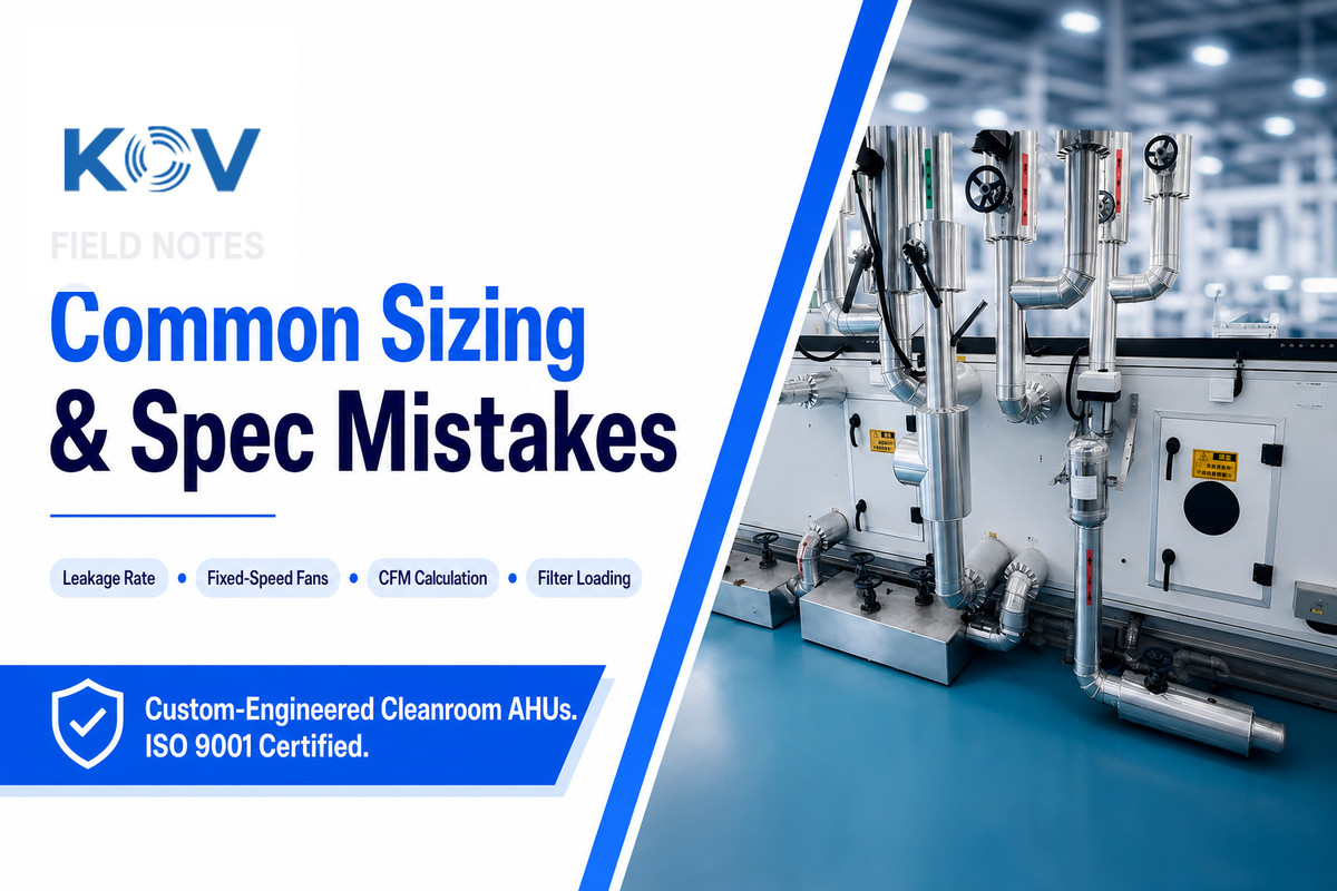
One published paper from a pharma industry conference on failures in cleanroom HVAC design documented one facility, in particular, had higher than expected leakage that required significant quantities of additional pressurisation air just to achieve and hold setpoint. This led to increased dehumidification loads and pressure attainment failures which had no basis in the initial design specification. As it turned out, the original leakage rate assumption which preceded the build (a cleanroom construction, a cleanroom engineering failure not a cleanroom HVAC equipment failure) was the real issue when the finished room was eventually measured up – a pattern Lawrence Berkeley National Laboratory’s cleanroom energy-benchmarking research has documented across many facilities: design-stage assumptions rarely survive contact with the finished building.
These design considerations highlight why designing a cleanroom benefits from engaging the HVAC engineer early in the building design process, prior to finalizing the shell.
Field Notes
The one commonality among HVAC professionals on real cleanroom projects: ventilation and AC performance draw way more attention-and complaints-than refrigeration capacity. One engineer on a 7 ISO cleanroom said his work getting comfortable conditions in a process room had become frustrating; he just couldn’t get out of the 100% fan bank speed his HVAC systems needed to handle the worst-case load. He noted it wasn’t a shortage of refrigeration that caused the problem, but rather fixed speed fans (or fans undersized) for variable loads. In a different discussion, cleanroom hvac designers note a common commercial pattern that should be recognized before quoting jobs: when a client’s budget comes back well above your initial estimate, that’s usually a sign their performance expectations are higher than what you originally designed for; worth confirming before, not after, the contract is signed.
Sizing self-check before you submit an RFQ
- Did you size for actual room leakage or an assumed rate from a generic spec sheet?
- Did you select fan capacity based on average or worst-case load, and what speed rating do you’ve (variable or fixed)?
- Does your room air change rate calculation (volume times desired ACH of 60) equal the rate actually required by your target ISO class?
- If the room hasn’t been accessed in more than 3 years, have you incorporated an allowance for increased filter load associated with particulate corrosion/buildup?
Industry Outlook, What’s Changing in Cleanroom HVAC Compliance
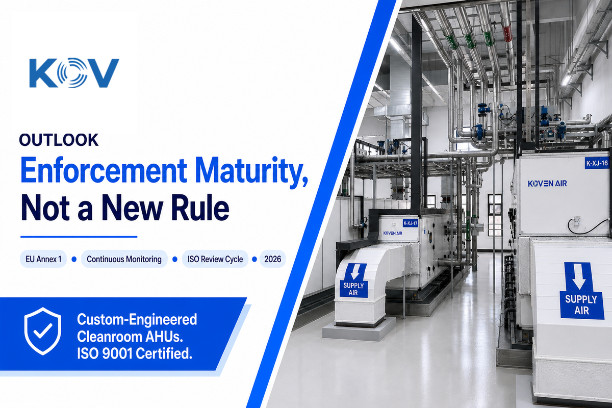
In 2026, it’s not so much about a brand new rule but about mature enforcement of existing rules. Since the EU’s updated Annex 1 was fully enforced in August 2024, regulators are now considering any system not relying on continuous data monitoring and logging as a relic of past practice rather than an accepted current standard. Because ISO 14644-1, the primary cleanroom standard (with ISO 14644-2 being its partner in this domain), is subject to ISO’s 5-year review process (current edition of-1 confirmed in 2021), it’s more likely that further clarifications-rather than an entire revamping-of the existing guidelines will come forth in the next few years, but it’s always good practice to check ISO’s website periodically for current revisions, even for older documents. Koven Air’s own commissioning teams have watched auditors’ baseline expectations shift over the last two years: the risk for buyers now isn’t a missing pressure gauge, it’s a missing log file.
Market-context only: independent market-research estimates put the global cleanroom HVAC market in the $59-63 billion range for 2025-2026, with most forecasts projecting continued growth through the early 2030s, directional background, not a substitute for your own facility-specific investment case.
Frequently Asked Questions
Q: What Are Cleanroom Standards?
View Answer
“cleanroom standards” refer to the criteria within ISO 14644-1, a standard that measures particle count in a room. In addition to this standard, regulations like EU GMP Annex 1 and US 21 CFR 211 build upon the requirements of cleanroom standards with regulations concerning pressure, monitoring, and handling procedures. The complexity is that no single standard governs every aspect of the space, and a compliant facility is built against several of them at once.
Q: What is a Cleanroom Environment?
View Answer
An environment with controlled atmospheric parameters, such as particle concentration (and often microbial contamination, humidity, temperature, and pressure) within designated limitations to support a manufacturing or research operation. Its primary purpose is preventing contamination of the product by operators, equipment, and materials of construction, not ensuring occupant comfort.
Q: What are the benefits of a preventative maintenance contract for cleanroom HVAC?
View Answer
The system integrity tests scheduled (e.g., for filter integrity, calibration of instrumentation, mechanical checks) identify degradations before they show up as an out-of-specification finding during an audit or batch. When a failure requires a reactive maintenance response (i.e., responding to an incident after it occurs) versus proactive maintenance (scheduled checks to ensure the system is working as it should), costs are generally much higher in terms of unplanned downtime, re-validation, and in a paper-trail that auditors actively scrutinize: no active maintenance record for a room implies that it isn’t being monitored proactively.
Q: Why choose EC-fan cleanroom HVAC over fixed-speed AC-motor systems?
View Answer
Fixed speed fan bank must be designed for worst-case load — the rare time when every single process load, door, occupant spike is simultaneously active — and then run at full capacity, all day long, every day, whether actual demand calls for one-third or 90% of that capacity. That’s an expensive habit — the fan is spending most of its service life burning electricity for a contingency that rarely (or never) occurs, without ever actually adapting to the actual load on the room. EC fans with VFD’s avoid this problem by adjusting speed to actual demand instead of default high-output, which allows precise control of temperature and humidity through cleanroom air conditioning without burning peak power 24/7. Independent retrofit data commonly puts savings in the 15-40% range just for fan energy — less than, and separate from, the 30-50% total building heat-recovery savings figure listed above — and EC fan equipped cleanrooms are also noticeably quieter and more comfortable for the occupants because they aren’t continuously fighting to meet worst-case load conditions.
Q: What are Semiconductor Cleanrooms, and do they need different HVAC than pharma?
View Answer
Semiconductor cleanrooms are optimized for clean air areas (ISO 1-4) in which contamination risk from sub-micron particle contamination is the primary concern, not microbial contamination. This dictates maximal unidirectional airflow and ulpa-grade filtration through out the ceiling. By contrast, pharma HVAC has to balance particle risk against microbial risk, as well as effects of humidity on the product, and specific regulatory requirements (GMP paperwork) not encountered in semiconductor fab. Underlying components (fans, coils, filters, controls) are the same but design targets are dramatically different.
Q: How is a cleanroom HVAC system different from other HVAC systems?
View Answer
A standard commercial hvac system will target basic comfort — acceptable temperatures and adequate fresh air — and energy costs. A cleanroom hvac system incorporates zoned pressure differentials (not just whole-building), multi-tier filtration to HEPA/ulpa grade, numerous air changes per hour beyond those needed for comfort, and monitoring/audit-trail logging built to survive a regulatory audit. There’s some overlap in product families and equipment, but the design targets and validation burden aren’t comparable.
References & Sources
- ISO 14644-1:2015, Cleanrooms and Associated Controlled EnvironmentsInternational Organization for Standardization
- Revision of EU GMP Annex 1, Manufacture of Sterile Medicinal ProductsEuropean Commission
- 21 CFR 211.46, Ventilation, Air Filtration, Air Heating and CoolingUS Food and Drug Administration
- EU GMP Annex 1 Guideline OverviewGMP Compliance Adviser
- Cleanroom Energy Benchmarking ResultsLawrence Berkeley National Laboratory
- How Does a Cleanroom Split System DX HVAC WorkCleanroom Technology
Why We Write This
Koven Air’s cleanroom retrofit data from pharmaceutical and biotech facilities was used in conjunction with independent engineering literature, standards, and reports; not just in-house sales claims. We’ve explicitly noted areas where independent sources offer divergent opinions — such as the service life of HEPA/ulpa filters or ceiling-coverage percentage for HEPA – rather than stating one particular number as definitive.
Reviewed by the Koven Air technical team
Related Articles
- Cleanroom AHU (Pharma/Biotech)Koven Air’s full cleanroom AHU product line, EN 1822 filter-class-to-GMP-grade mapping, and GMP retrofit case studies
- The Complete Guide to Commercial Air Handling Unitshow commercial AHU selection differs from cleanroom-grade requirements
- GMP Grade Filter Matchermatch your target GMP Grade to the correct filtration stage
![Cleanroom Dry Cooling Coil: How It Works [2026 Guide]](https://kovenair.com/wp-content/uploads/2026/07/cleanroom-dry-cooling-coil-guide-featured-2-768x512.png)

![Commercial Rooftop Unit Guide: Types, Sizing & Costs [2026]](https://kovenair.com/wp-content/uploads/2026/07/commercial-rooftop-unit-guide-featured-2-150x150.png)