
Get in Touch with Koven Air Company

ISO 14644 / EU GMP ANNEX 1
Pharmaceutical Dry Cooling Coil (DCC) for GMP Process Areas
Pharmaceutical dry cooling coils from Koven Air remove sensible heat from GMP process air without producing condensate. The coil surface never drops below the room dew point, eliminating drain pans, standing water, and microbial growth risks in your A/B/C/D-grade cleanrooms.
Full Traceability
SS316L Sanitary Build
Closed-Loop Ctrl
13°C
CHW Supply
0.0
Condensate Risk
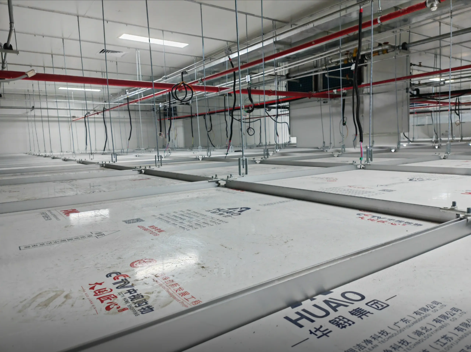
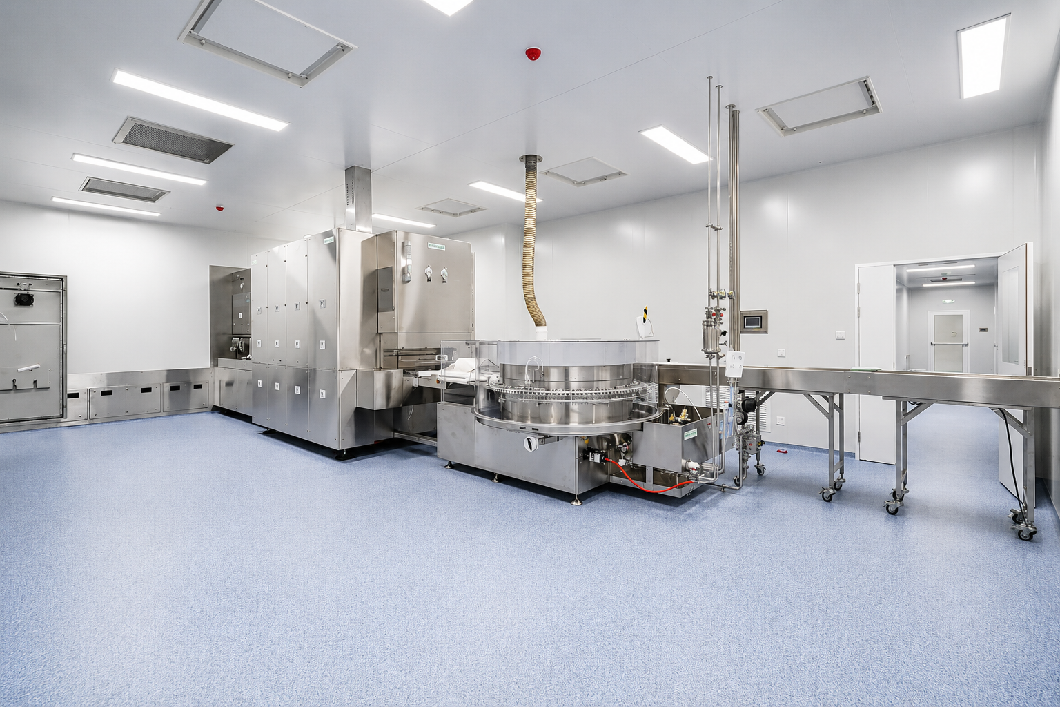
Technical Dashboard & Parameters
53.3 kW
Sensible Capacity
±1.0°C
Closed-Loop Precision
13–14°C
Chilled Water Supply
2.0°C
Design Air ΔT
4.5×2.1m
Coil Footprint (4-Row)
SS316L
Wetted Component Grade
Condensation Risk in Pharma Process Areas, How a Dry Cooling Coil Solves It
What’s so “Dry” about a DCC? A pharmaceutical DCC is simply a chilled-water coil that removes only sensible heat (temperature), never latent heat (moisture). Its coil surface is kept above the room’s dew point so water doesn’t condense on it. That single design difference is arguably more significant in a GMP cleanroom than just about anywhere else in a building.
Condensation forming on a coil surface, drain pan, or duct will become a standing-water reservoir, a direct route for microbes in an A/B/C/D-rated zone, that any Contamination Control Strategy compliant with EU GMP Annex 1 §2.3 needs to address. Even the best wet coil setups require a drain pan and routine sanitation. DCC eliminates the risk at the coil.
Because we make GMP process cooling gear, Koven Air designs process dry coils with that job in mind – using sanitary grade surfaces, chilled-water loops set up to run at least 2°C above the dew point during the average process load, and control loops tight enough to keep a cleanroom fill area’s grade-A area within 1°C of target.
And it’s a sensible-only process dry coil design from the start, not a cleanroom AHU dry-run retro fit, where the over-size surface area leaves control to an off-hand tuned control loop.
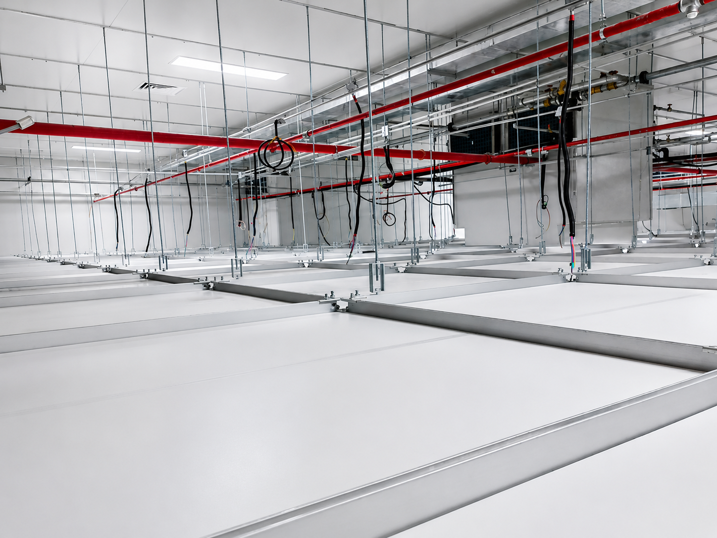
0%
LATENT MOISTURE
Below we lay out the specs, describe an actual 54-coil plant installation, and detail the records that go into your validation file.
Koven Air Pharma Process Dry Coil, Configurations & Specifications
The units are 4-row, vertical mounting assemblies that are 4.5m (L) x 2.1m (H) x 0.36m (thick), mounted at an orientation we call W-angle, whereby arrays of them form a unified plane along the return-air corridor, an arrangement that we at Koven Air adopted for no other reason than ad-hoc spacing is why first-installs almost inevitably generate service-access issues. We design for at least 1.0-1.25m service clearance on the front of each coil and we place the arrays 1.25m from the exterior wall-those are dimensions straight out of a biopharma installation, not the latest catalogue.
The control strategy at work here, that’s used for decoupling control, also known as THIC (temperature and humidity independent control) works as follows; DCC for sensible, MAU for latent/humidity and FFUs for particulate – three separate systems with three different purposes not interfering with each other’s set point.
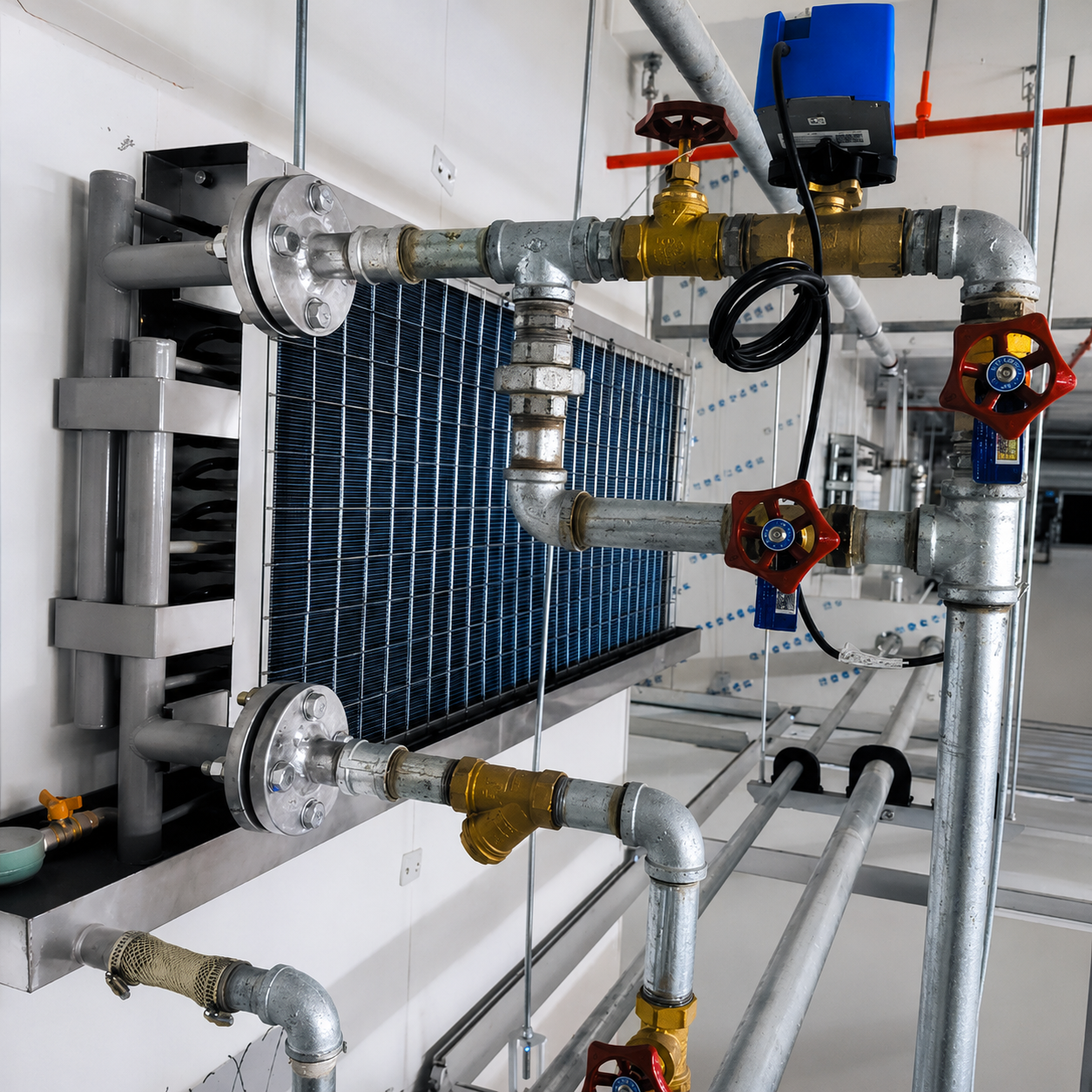
SYS. ARCHITECTURE
For a reality-based example of that, the 1.25m dimension off the wall is often the first thing the site team fights; we specified it to make coil-bank withdrawal possible for cleaning without disabling the circuit next to it.
Where more common elsewhere, combined AHU coils are tasked to control both latent and sensible load in one shared airstream, which works, but it requires those coils to condense and re-heat that shared airstream simultaneously, exactly the drain-pan/microbial pathway this page opened with.
| Parameter | Value | Note |
|---|---|---|
| Sensible cooling capacity | 53.3 kW per unit | Includes ~2% hydraulic-imbalance margin |
| Chilled water temperature | 13–14°C supply / 18–19°C return | Mid-temp circuit, held above dew point |
| Design air ΔT | 2.0°C (range 1.5–2.5°C) | Sensible-only, dry-operation heat exchange |
| Control precision | ±1.0°C (A-grade), ±1.5°C (C-grade), ±2.0°C (D-grade) | PT100 (±0.1°C) + PID loop on motorized valve |
| Wetted materials | SS316L / SS304 corrosion resistant stainless steel, copper coil tube | Silver-brazed tube joints, project-spec grade |
| Pressure test | ≥0.6 MPa, 30-minute hold, ≤0.02 MPa drop | Per-unit factory test before shipment |
GMP Cleanroom Class → Dry Coil Sizing Matrix
Fresh out of a recently completed 2000m² biopharma fill-finish project – it’s the next closest thing to an actual answer you can get to “how many DCC units do I really need for my cleanroom class?”
| Cleanroom Grade | Area | DCC Units | Zone Capacity | Control Precision | Relative Humidity |
|---|---|---|---|---|---|
| Grade A (B-background fill core) | 580 m² | 16 | 853 kW | ±1.0°C | ≤45±5% RH |
| Grade C (fill support/prep) | 880 m² | 24 | 1,279 kW | ±1.5°C | 55±5% RH |
| Grade D (auxiliary) | 540 m² | 14 | 746 kW | ±2.0°C | 55±10% RH |
| Total | 2,000 m² | 54 | ≈2,878 kW | — | — |
Source: Koven Air completed project data, GMP biopharma sterile fill-finish facility, EU GMP Annex 1 (2022) A-core/B-background classification. Grade-to-ISO 14644-1 equivalence (Grade A = ISO 5 static/dynamic; Grade C = ISO 7 static/ISO 8 dynamic; Grade D = ISO 8 static) is the project’s own classification per standard industry cross-reference — Annex 1 sets its own particle-count table rather than citing ISO class numbers directly.
Not sure how many units your cleanroom footprint needs?
Request a Sensible Heat Load Calculation →Dry Coil vs. Conventional Wet Cooling Coil, Contamination Risk Comparison
A standard wet coil chills air below its dew point, where it then condenses, then you drain off the moisture through a drain pan and condensate line, and finally schedule regular cleaning and sanitation to make sure that moisture doesn’t become a contamination source.
A dry coil is engineered so the coil’s surface temperature never drops below the dew point; in essence, the condensation-control duty shifts from “handle it after it forms” to “don’t let it form.” Here’s the comparison we walk engineering teams through most often:
FACTOR [VAR]
WET COOLING COIL
KOVEN AIR DRY COIL (DCC)
Chilled water supply temp
6–7°C (below dew point by design)
13–14°C (held above dew point)
Condensate produced (design operation)
Yes — requires drain pan + condensate line
0% — no drain pan required
Microbial growth substrate
Standing condensate on coil/pan
None generated by the coil itself
Humidity control
Coil handles both sensible + latent load
Decoupled — MAU handles latent/humidity separately
Cleaning/sanitization interval
Drain pan + coil face on a fixed schedule
Coil face only, no standing-water cycle
Air-side ΔT
8–12°C
2.0°C design (1.5–2.5°C range)
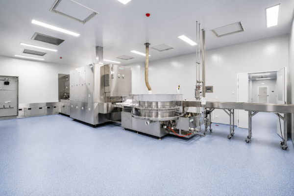
AHU heat-recovery systems suffer real-world efficiency loss from parasitic leakage and bypass when they try to do both sensible and latent load on a single circuit, that’s documented in peer-reviewed HVAC literature, not just sales talk. A dry coil can’t fail that way: there’s no recovery loop to leak, and no condensate cycle to foul and progressively lower the coil’s rating. Cleanroom energy use runs 30-50x that of conventional buildings, with HVAC accounting for 40-60% of that load, so the efficiency difference between a combined coil and a dedicated sensible-only coil adds up fast. It’s as much a maintenance argument as a contamination-control one, and it’s the one that always lands with plant managers.
We don’t have a formal multi-year field service life study with which to cite a definitive service-life multiplier, and so we won’t make one up. The factual takeaway is that a coil that doesn’t condensate at all doesn’t suffer from the condensate-borne biofilm or mineral fouling on its face that typically dictates frequency of coil face cleaning in cleanroom service on wet coils. We can also report factually from observation in the field, service cycle intervals on dry-operation coils tend to be longer than wet-operation coils doing the same work.
Dry coil condensation control works fine under design, but is no substitute for humidity control (MAU) when conditions are off: a broken MAU damper, an abnormally humid day when make-up air must be introduced – cold surface condensation returns as the coil does what it’s supposed to do, but the air arriving no longer fits the design model. That’s the honest version of the sensible-latent trade-off: we won’t claim a dry coil alone handles humidity, because it doesn’t. That’s why we propose the DCC as one part of a three-legged THIC (temperature humidity independent control) architecture, not a self-standing solution.
Want to check dry coil performance in your particular cleanroom classification?
REQUEST A CUSTOM COMPARISONCase Study: 54-Unit DCC System for a GMP Biopharma Fill-Finish Cleanroom
PROJECT OVERVIEW
Designed for a new-construction, sterile cleanroom facility. We decoupled the HVAC infrastructure utilizing a 3-way THIC architecture to ensure pinpoint accuracy across the large-scale A-grade zone.
APPLICATION
Freeze-Dried Antibody Filling
COMPLIANCE
EU GMP Annex 1 (2022)
THIC ARCHITECTURE
MAU + DCC + FFU
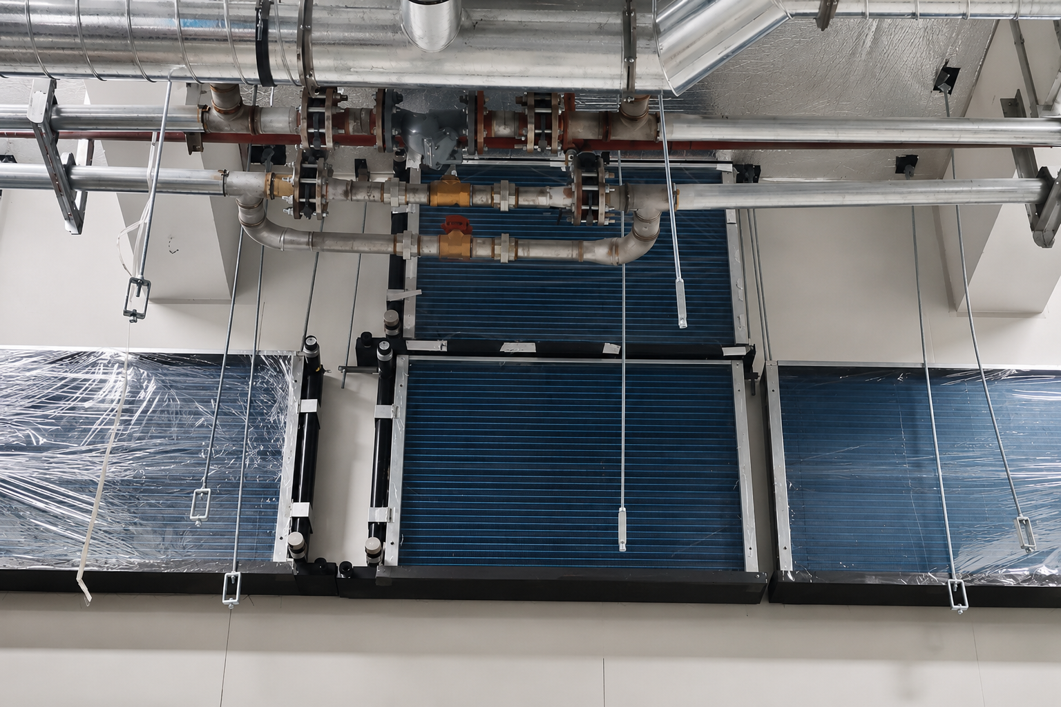
THE ENGINEERING CHALLENGE
While PID controllers manage the chilled water flow via motorized valves to maintain a strict 1.0°C tolerance, the actual challenge across a 580-meter zone was purely hydraulic.
“With 54 units on one circuit, the worst-case loop is 280m and the best is 16m. Without dynamic balancing on a reverse-return layout, short loops short-cycle and long loops starve. The best PID still hunts if starved of flow.”
— Senior Application Engineer, Koven Air
SYSTEM SPECIFICATIONS
TOTAL DCC UNITS
54 (27 N / 27 S)
INSTALLED CAPACITY
≈2,878 kW
HYDRAULIC BALANCING
Reverse-return + Dynamic
LOOP LENGTH (MAX/MIN)
~280 m / ~16 m
IMBALANCE TARGET
≤15% (Diff ≤10%)
COMMISSIONING & VALIDATION
-
Aerosol Challenge: 100% PAO/DEHS scan testing (≤0.01% penetration)
-
Particle Counting: At-rest & in-operation per ISO 14644-1
-
Pressure Cascade: Room-to-room differential testing
-
Hydraulic Test: ≥0.6 MPa held 30 mins (≤0.02 MPa drop)
Standards & Compliance: EU GMP Annex 1, ISO 14644, EHEDG/ASME BPE
01. REGULATORY CONTEXT
Utilities qualification (water, HVAC, compressed gases) is now an explicit line item on pharmaceutical procurement checklists, separate from general equipment qualification, because auditors have cited missing or vague utility-system records often enough that it has become its own designated category.
Koven Air’s compliance package is built to the equipment-qualification logic in 21 CFR 211.63 (design, size, location) and 21 CFR 211.65 (non-reactive/additive surfaces)—the specific regulatory language US auditors check against.
02. VALIDATION CADENCE
The requalification cadence follows the same Annex 1 criteria your validation team uses today. Grade A and Grade B areas will need to be requalified at no more than a 6-month interval, with Grades C and D requiring no more than a 12-month interval. Every DCC is sized and documented to match your schedule.
03. CERTIFICATION MATRIX
Quality Management
ISO 9001:2015
Environmental Mgmt
ISO 14001:2015
Occupational H&S
ISO 45001:2018
European Conformity
CE Marking
Healthcare HVAC
DIN 1946
04. DESIGN STANDARD STACK
-
EU GMP Annex 1 (2022) – Grade definitions (A-D) at section 4.4; positive-pressure supply with ≥10 Pa differential (sec 4.14); airflow visualization (sec 4.15); continuous monitoring (sec 4.16); CCS integration (sec 2.3).
-
ISO 14644-1/2/3/4 – Particle classification, performance monitoring, testing methods (including PAO/DEHS filter-leak testing) and design/startup guidance.
-
EN 1822 / ISO 29463 – HEPA filter and ULPA filter classifications applicable to the fan-filter-unit layer of the THIC architecture.
-
EHEDG / 3-A / ASME BPE – Sanitary design and surface finish criteria applicable to wetted coil components.
05. DOCUMENTATION
Do you need a complete package of your coil certification and compliance documents for your quotation file?
REQUEST DETAILED RECORDS →Ordering a Pharma Process Dry Coil, Material Traceability, Lead Time & Validation Support
The biggest concern voiced by our customers sourcing non-domestic equipment for GMP applications is not the technical performance of the coils; it’s the potential risk posed by the supplier’s compliance documentation. This is a well-documented finding in real FDA inspection reports (“approved suppliers have not been requalified since [date]” and missing supplier-qualification procedures being among the most common), not a phantom risk.
Our commitment to traceability ensures that from the mill certificate of the raw materials used to your project handover file, we have a documented history, not just an after-the-fact certification.
“Koven Air documents each coil against the exact cleanroom grade that unit will be shipped to… providing on-site installation and commissioning support where drawings and reality diverge.”
Material Traceability Chain (Standard on Every Coil)
Every serial-numbered coil ships with component-level records drawn from a representative project traceability sequence:
Raw Material Supplier
→
Mill Certificate
→
Incoming Inspection
→
Work Order
→
Coil Assembly
→
Pressure Test
→
Clean Pack
→
Finished Coil Serial Number
→
Project Handover File
SYS. VALIDATION DATA
Component
Material Grade
Standard
Heat/Batch No.
Inspection
Drain Pan
SS316L
ASTM/EN
H25-7841
IQC-082
Coil Tube
Copper Tube
ASTM/EN
C25-1190
IQC-119
Frame
SS304
ASTM/EN
S25-2236
IQC-223
Brazing
Silver Alloy
Project Spec
B25-601
W-Log-601
Source: Koven Air Material Traceability Records (Example Project)
Pricing Configuration Factors
The cost of coil components in a GMP project varies with several independent variables, rather than a single fixed per-unit price:
- Cleanroom Grade: Holding a Grade A tolerance requires tighter control loops than Grade D.
- Sanitary Specs: SS316L vs. SS304 wetted surface material choices.
- Hydraulic Complexity: Number of units and reverse-return balancing layout.
- Validation Support: Standard documentation package vs. full IQ/OQ/PQ support with 3rd party witnessed testing.
Engineering & After-Sales Support
Unlike commodity suppliers who treat sensible cooling coils as universal drop-ins, we run rigorous pre-sales professional calculations to verify parameters prior to issuing a quotation. Post-production, units are shipped only after testing validates zero performance issues.
WARRANTY & ON-SITE SERVICE:
During the warranty period, we provide free technical service support to address any field issues without delay, offering ongoing professional training to contractors and your on-site engineering team.
During the warranty period, we provide free technical service support to address any field issues without delay, offering ongoing professional training to contractors and your on-site engineering team.
Engineering Tools & Compliance Resources
[SYS] THERMAL
Heat Load Calc
[SYS] DEW POINT
Condensation Margin
[QA] ANNEX 1
Compliance Check
[TECH] ARCH
Wet vs. Dry
Frequently Asked Questions
What is a dry cooling coil (DCC)?
How dry coils work Dry cooling coils transfer sensible heat from process air using chilled water which is maintained above the space dew point. In doing so, moisture does not condense on the coil surface, unlike a standard cooling coil where it does.
What is DCC in a GMP cleanroom context?
What DCC means in pharmaceutical HVAC In the context of Pharmaceutical HVAC, DCC means a Dry-operation Coil which functions for the sensible-cooling leg of a Temperature/Humidity Independent Control (THIC) system. DCC coils typically partner with a make-up air unit (MAU) for humidity control and FFU’s for particulate control, like the system in our 54 unit case study above.
Why doesn’t a coil supplied at 13–14°C condense, even when the room’s dew point is higher in some conditions?
To achieve this, the supply and return water temperatures to the coil are selected so that the coil surface temperature will be about 2 °C above the conditioned space’s dew point during normal operation. As the coil surface temperature tracks the water temperature, not the air temperature in the room, condensation is avoided. However, this is only guaranteed within the design envelope, not in conditions outside the assumptions.
What is the difference between a wet coil and a dry coil?
A wet coil receives chilled water cold enough to drop air below dew point, deliberately creating moisture condensation (working like a humidifier too) and therefore requires a drain pan and condensate line. A dry coil receives warmer chilled water set at a level to prevent it dropping the air below the dew point and thus just achieves sensible cooling without producing condensate.
Is the dry coil compatible with WFI-critical zones?
Yes, our sanitary design (SS316L wetted parts, silver-brazed connections, cleanable framework) and no condensate application are designed for the demands of the Water-for-Injection periphery and similar GMP-critical locations where standing water creates a risk. Please check with our engineering team about your specific WFI zone application, regarding required material specifications and validation status.
What GMP standards does Koven Air design DCC systems to?
- EU GMP Annex 1 (2022) For Grade / Pressure-Cascade / Contamination control requirements
- ISO 14644-1/2/3/4 For Classification & testing of cleanrooms
- EN 1822 / ISO 29463 For the HEPA/ULPA filters on the paired FFU layer
- EHEDG / 3-A / ASME BPE For surface and construction.
What lead time should we expect for a custom GMP dry coil order?
Unit numbers, sanitary material, and the level of validation record needed can influence lead-times – contact our engineers for a quote and lead-time estimation after your cleanroom grade and layout is decided.
Can Koven Air provide IQ/OQ/PQ validation support?
Yes. Factory tests (pressure test, valve/electrical function checks), and material trace reports flow right into your Installation Qualification package, and our engineers provide onsite support with commissioning and collecting the data your validation team needs to collect during Operational/Performance Qualification.
What is the purpose of a cooling tower or chilled water source in a pharma HVAC system?
A chilled water plant (chiller + distribution loop) supplies the mid-range water temperature — 13-14°C in our example — that flows through the dry coil to extract sensible load. This plant is a stand-alone item of equipment, balanced project-wide with the DCC array in the hydraulic-balance case study above.
Does a dry coil eliminate humidity control, since it doesn’t dehumidify?
No, a dry coil intentionally has nothing to do with humidity control. In a THIC setup, dehumidification and latent load is done by the MAU, leaving the dry coil to concentrate solely on sensible temperature control.
![Commercial Rooftop Unit Guide: Types, Sizing & Costs [2026]](https://kovenair.com/wp-content/uploads/2026/07/commercial-rooftop-unit-guide-featured-2-150x150.png)