
Get in Touch with Koven Air Company

ISO 9001 Certified
Concealed Fan Coil Unit
Concealed Fan Coil Units (Ducted, KAFP Series)
Above your ceiling and just under the floor plate, a concealed fan coil unit will whisper clean, ducted-chilled heating and cooling-nine KAFP models complete with published duct-sizing data, and a 2,232-unit field record spanning over 6 years.
- 2-Pipe Chilled/Hot Water
- 42–56 dB(A) Noise @50Pa
- Published Duct-Sizing Data
- Proven High-Rise Deployment
9
KAFP Models
200–1401
CFM Range
2,232
Units in One Deployment
6+ yrs
Field Data on Record
Noise Complaints Above the Ceiling? How a Concealed Fan Coil Unit Solves It
A concealed fan coil unit is a horizontal ducted fan-coil that installs either in a bulkhead or above a suspended ceiling. As such, none of the actual equipment ever appears in the occupied space-just a few short supply/return duct runs and an unobtrusive grille. A fan pushes conditioned air over a copper-tube/aluminum-fin coil which in turn circulates chilled or hot water to heat and cool that air before sending it out through the short duct.
A concealed FCU is engineered to fix the problem a surface-mounted ceiling-cassette or wall-hung unit creates in an occupied room: even a unit meeting a 35 dB(A) noise target can become the single loudest object in the room, because its coil and fan sit exposed without the acoustic and concealment benefit of a plenum space. That’s not a marketing distinction — retrofitting concealment after the fact typically means opening finished ceiling and rerouting duct, losing days of occupied-space downtime that planning for a concealed layout from day one avoids entirely. Ducted equipment like the KAFP series is rated to AHRI Standard 260, the sound-rating standard that specifically covers ducted air-moving equipment rather than the non-ducted rating some competing listings misapply. Koven’s KAFP line solves the concealment problem by moving the coil and fan out of the completed room space altogether, leaving only the grille and a short duct run below the floor plate.
Buyers looking for FCUs typically express two primary concerns even before opening the product catalog to find the specification table: not being able to find a concealed unit in the precise CFM/tonnage needed (and consequently over- or under-sizing), and a lack of confidence that the duct connector on the building side will mate cleanly with the outlet plenum on the unit itself. Koven’s KAFP Two-pipe Series addresses both issues with nine different models and a detailed, duct-sizing table-including round and rectangular dimensions for each model-a table many manufacturers exclude from their product specification data on their web pages.
This basic conflict shows up in different forms across building types. The operator of a hotel facility might need a unit to disappear in a hotel corridor but can’t spare much space in a tight 460 mm ceiling plenum, making Koven’s 240 mm KAFP chassis the appropriate choice for a tighter plenum size. For a hospital, laboratory, or medical-suite owner, a hospital-level unit needs to provide access for service in a wall, without violating required clearance parameters for maintenance personnel-but Koven’s KAFP line can achieve this if properly designed for accessibility. For the landlord of an office space in the midst of a tenant fit-out, the key issue is providing equipment that will adapt as the original open plan is repartitioned into smaller private offices, a process that inevitably changes airflow dynamics to something that wasn’t anticipated during the initial design. In each of these commercial-building applications, what distinguishes a successful choice from a poor one isn’t the fan coil itself, but rather the presence of clear, accessible duct-sizing and clearance data at the point of selection — information Koven Air makes available in Table 1 and Table 2 below, free of the ISO-paperwork runaround some suppliers require just to release a spec sheet; if your project doesn’t match a standard configuration, request a quote and we’ll size it with you directly.
KAFP-SERIES
KAFP Two-Pipe Series, 9 Models & Selection Data
Spanning 200 to 1,401 CFM across nine chassis sizes, the KAFP range covers this in fine steps. Each chassis features a 3-row copper tube / aluminum fin coil, 3/4″ (DN20) water and condensate connections, and three external static pressure speed taps (12/30/50 Pa). All units are factory-tested, AC-motor-driven, and this table represents the entire published range, unlike catalogs that show only their best-selling sizes and quote the rest on request.
One of the most costly mistakes to make is selecting a unit with more or less capacity than required for the space served – specifying a unit rated for 300 CFM when the load actually requires 400 CFM won’t only result in an insufficient or excessive power delivery and increased noise trying to keep up, it can leave the space up to 2-4°F away from setpoint on the hottest days of the year, leading to occupant complaints returning to the mechanical contractor months after turnover. Koven’s KAFP range avoids this gap by incrementing in 100-200 CFM sizes, instead of the wider leaps typical in smaller competitor lines, so you’re almost guaranteed to find the exact capacity needed for your load calculation on the chart – not just the next nearest thing that will do the job. This level of granularity becomes increasingly critical to buyers with small capacity requirements, as installer forums are quick to point out that there’s almost nothing available in the US market that comes close to matching a small concealed-FCU load without upsizing to a much larger chassis. Koven’s 200 CFM KAFP-02WA entry point is designed specifically to bridge that gap.
Table 1 — KAFP-02WA to KAFP-14WA Performance Data (2-pipe, AC motor)
| Model | Airflow High (CFM) | Cooling (BTU/h) | Heating (BTU/h) | Water Flow (GPM) | Fan Qty | Connections | Noise @50Pa dB(A) | Weight (lb) |
|---|---|---|---|---|---|---|---|---|
| KAFP-02WA | 200 | 7,370 | 11,055 | 1.61 | 1 | 3/4in (DN20) | 42 | 31 |
| KAFP-03WA | 300 | 10,871 | 16,306 | 2.42 | 2 | 3/4in (DN20) | 44 | 33 |
| KAFP-04WA | 400 | 14,249 | 21,373 | 3.22 | 2 | 3/4in (DN20) | 46 | 33 |
| KAFP-05WA | 500 | 16,889 | 25,334 | 3.72 | 2 | 3/4in (DN20) | 47 | 40 |
| KAFP-06WA | 600 | 20,267 | 30,401 | 4.52 | 2 | 3/4in (DN20) | 49 | 42 |
| KAFP-08WA | 800 | 27,023 | 40,535 | 6.03 | 3 | 3/4in (DN20) | 50 | 62 |
| KAFP-10WA | 1,001 | 31,629 | 47,444 | 7.04 | 3 | 3/4in (DN20) | 50 | 66 |
| KAFP-12WA | 1,201 | 37,587 | 56,380 | 8.34 | 4 | 3/4in (DN20) | 54 | 73 |
| KAFP-14WA | 1,401 | 43,851 | 65,777 | 9.74 | 4 | 3/4in (DN20) | 56 | 79 |
High speed performance, 3-row copper-tube/aluminum-fin coil, 232 psi (1.6 MPa) maximum working pressure, 0.05/0.12/0.20 in.w.c. (12/30/50 Pa) external static.
The KAFP 9-Model Airflow-to-Duct Sizing Key
An oversized duct penalty can turn even the best performing concealed FCU on its back – on the bench it’s perfect, but once installed it won’t achieve rated airflow while trying to push air through a duct that’s too small. Koven provides the correct round and rectangular duct sizing for every KAFP unit per SMACNA’s recommended friction-rate design method (supply designed at approx 700 FPM, return at approx 600 FPM for quiet operation), eliminating guesswork for your ductwork designer.
| Model | Airflow (CFM) | Supply Round | Supply Rect. | Return Round | Return Rect. | Min. Supply–Return Separation |
|---|---|---|---|---|---|---|
| KAFP-02WA | 200 | 8in | 6×8 | 8in | 6×8 | 3.5 ft |
| KAFP-03WA | 300 | 9in | 8×8 | 10in | 10×8 | 3.5 ft |
| KAFP-04WA | 400 | 12in | 12×8 | 12in | 12×8 | 4 ft |
| KAFP-05WA | 500 | 12in | 14×8 | 14in | 16×8 | 4 ft |
| KAFP-06WA | 600 | 14in | 16×8 | 14in | 18×8 | 4 ft |
| KAFP-08WA | 800 | 16in | 22×8 | 16in | 24×8 | 5 ft |
| KAFP-10WA | 1,001 | 18in | 26×8 | 18in | 32×8 | 5 ft |
| KAFP-12WA | 1,201 | 18in | 32×8 | 20in | 38×8 | 5 ft |
| KAFP-14WA | 1,401 | 20in | 38×8 | 20in | 44×8 | 5 ft |
All transitions and reducers will be manufactured per SMACNA design standards, 15° per side divergence (expansion), 30-45° per side convergence, and transition length = 1.5x (sum of connecting dimensions/2). Galvanized duct gauge per SMACNA low pressure standards: 26 ga typically to 18″, 24 ga 19″-30″, and all joints sealed to SMACNA Seal Class A.
Table 4 — Duct & Pipe Insulation Options
Insulation selection and duct gauge follow the same engineering guidelines, because a correctly sized duct is meaningless if insulated poorly, resulting in condensation or loss of thermal performance. Closed-cell material (FEF/PEF) is specified for chilled-water branch ductwork specifically to address condensation control.
| Material | k-value W/(m·K) | Fire/Smoke | Moisture Resistance | Typical Use |
|---|---|---|---|---|
| Flexible elastomeric foam (FEF) | 0.034–0.036 | 25/50 (B1) | Excellent (closed-cell) | First choice — chilled duct & pipe |
| Fiberglass (duct wrap/board) | 0.036–0.043 | Class A | Poor (needs FSK facing) | With vapor barrier; also acoustic |
| Mineral/stone wool | 0.037–0.045 | Class A | Poor (needs barrier) | High fire-rating areas |
| Polyethylene foam (PEF) | 0.035–0.040 | B1/B2 | Excellent (closed-cell) | Pipe & small duct |
| Phenolic foam (PF) | 0.022–0.030 | B1 | Good | Lowest k-value, highest efficiency |
Basis of selection: closed-cell material (FEF/PEF) for chilled water applications (to prevent condensation), Class-A materials where fire rating governs, others to comply with local energy code condensation-control requirements (e.g. IECC, ASHRAE 90.1).
Concealed vs Cassette vs Wall-Mounted, Which FCU Fits Your Ceiling?
Choosing between a concealed, cassette or wall-mounted unit really depends on what your ceiling and structure will support, not which will look best on a spec sheet – and getting that wrong will result in a structural problem, not a paint touch-up: a cassette that was specified into a 250mm void that required 300mm+ of structural depth will mean a change order, a delayed ceiling contractor, and mid-project redesign, not a quick fix. A standard horizontal concealed FCU needs around 280mm of ceiling void space to work (up to 460mm for larger, plenum-mounted versions, according to the ASHRAE Handbook’s room air-distribution chapter); a four-way ceiling cassette requires similar ceiling depth plus sufficient clearance around the unit’s sides for the discharge grille to work; and a wall-mounted unit has no need of a ceiling void at all, in exchange for having a cabinet mounted in the room. Fan coil noise is a function of fan size, external static pressure, return-inlet velocity and duct lining (according to ASHRAE), not an absolute property of a given mounting type; therefore, the real question for you isn’t “which is quietest” (as a brochure will tell you), but which type your structural design can accommodate. Koven engineers the KAFP chassis to the narrower end of that ASHRAE ceiling-void spectrum — the structural reason a 240mm unit fits more retrofit ceilings than a 400mm-plus cassette, a matter of a measurement you can verify against your reflected ceiling plan, not marketing hype. The trade-off you’re actually making is between form factor and access, not performance: a concealed unit gains ceiling clearance but needs an access panel for filter maintenance, a fair exchange once you see the numbers side by side, not an absolute property of a given mounting type. Koven’s own factory-tested spec data — not a competitor’s brochure claim — is what lets you check that trade-off against your own project before you commit to a model.
Table 3 — Concealed vs Cassette vs Wall-Mounted (design constraints, not marketing claims)
| Type | Ceiling/Wall Void Needed | Visible in Room? | Structural Support | Best Fit |
|---|---|---|---|---|
| Concealed (KAFP) | ~240–280mm ceiling void | No — short duct + grille only | Independent hanger rods to slab, per ASHRAE Ch.58 | Finished ceilings, hospitality/office corridors, no visible equipment allowed |
| Ceiling Cassette | ~280–460mm void + side discharge clearance | Flush grille visible in ceiling | Independent support, four-way air distribution | Open-plan rooms needing 360° air throw |
| Wall-Mounted | None (surface-mounted) | Cabinet visible on wall | Wall bracket only | Fast retrofit, no ceiling access available |
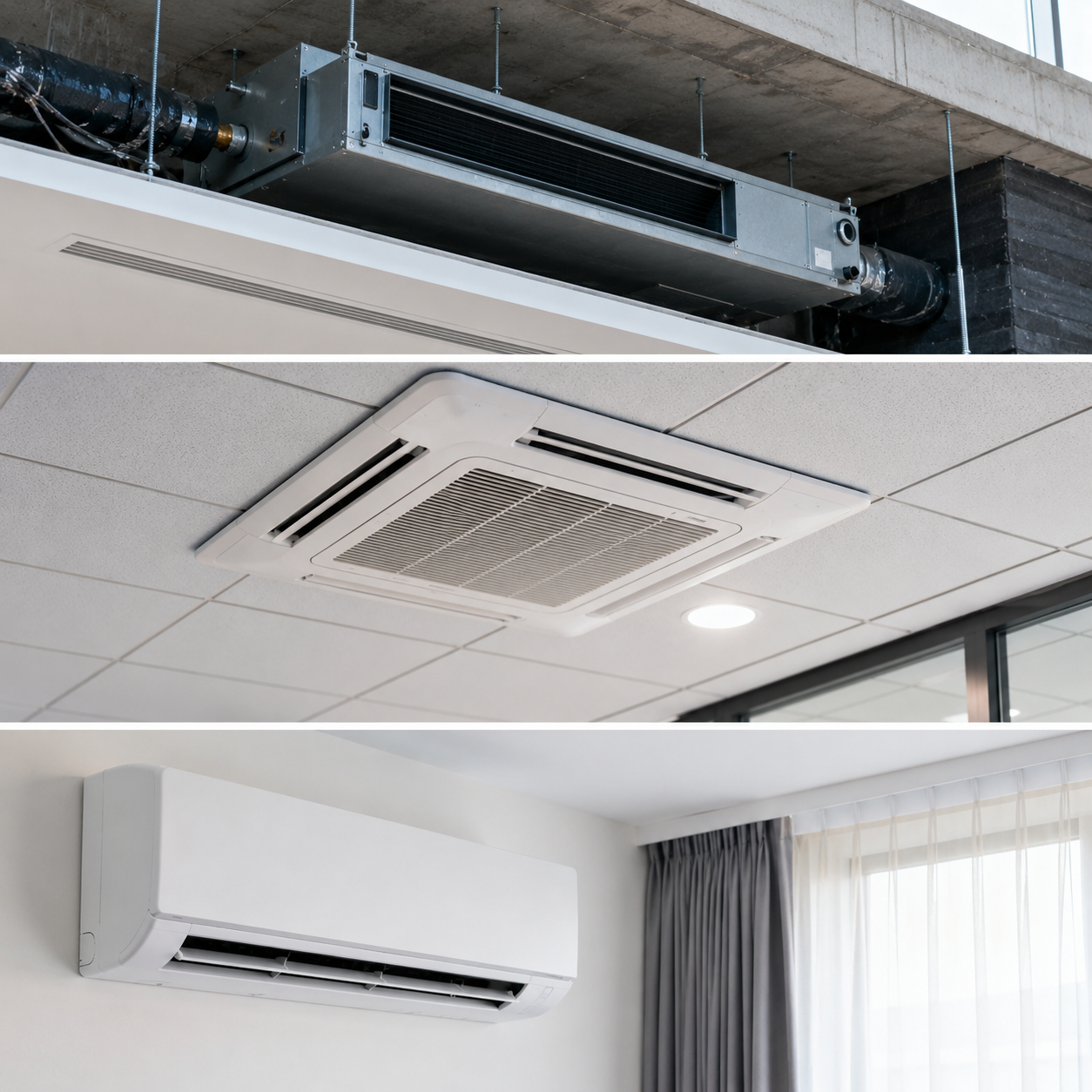
Comparing common types of fan coil units, the concealed and cassette variants both place the cooling coil above the ceiling, differing primarily in their discharge configuration and access, while both rely on a similar coil-and-fan design. Vertical stacking configurations sometimes appear in high-rise residential and hospitality towers, fitting between floors within the wall structure, not above a ceiling-a structurally distinct arrangement, outside the horizontal-ceiling scope covered by the KAFP series. Be careful not to confuse fan-coil units with blower coil units; the latter is a term commonly applied in the market (but not a standards definition) for draw-thru terminals that fall between a fan coil and a full air-handling unit, designed for higher airflows and static pressures than a concealed FCU like those in the KAFP series. If your cooling load calculation already exceeds the capabilities of the 9-model horizontal range, then you’re in a different equipment class than this product family addresses.
Proven at Scale, 2,232-Unit Deployment, 6+ Years of Field Data
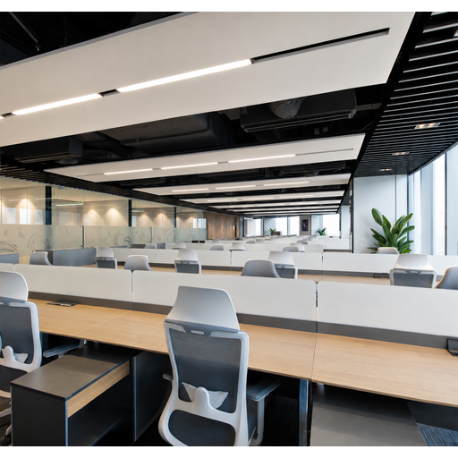
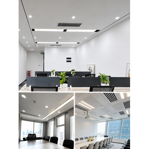
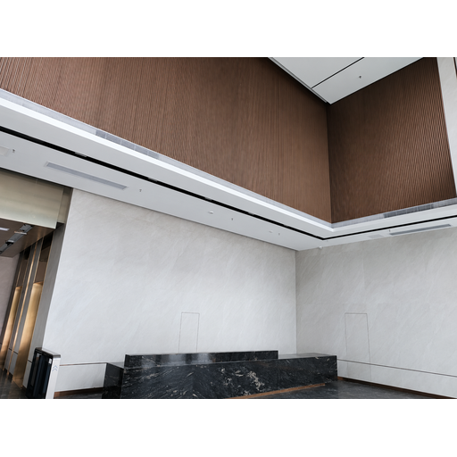
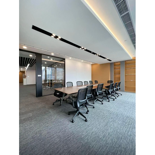
A major Shenzhen financial center – a 40-story, 229,986 square meter tower in the city’s Futian Central Business District that achieved China Green Building 2-Star and LEED-CS Gold ratings – selected Koven Air’s KAFP-series units to equip every office, meeting room, and reception area of the building, with a total of 2,232 units commissioned in December 2019. Commercial fan coil units on this scale rarely come with a full, multi-year performance record that’s valuable enough to be presented in detail, as opposed to a simple mention.
0.32%
Cumulative failure rate over 6+ years of operation (Dec 2019–2026) — vs. a 2% industry-average benchmark
Source: Koven Air project deployment record, Shenzhen financial center, 2,232 units
29–32 dB
Measured office noise (26–29 dB in meeting rooms)
25%
Below-industry-average terminal-system energy share (19.5% of total HVAC load)
96.8%
Occupant comfort satisfaction rate
<¥60
Annual maintenance cost per unit
Read this before the numbers below
This project used Koven’s DC brushless (ECM) variant of the KAFP horizontal concealed line, a distinct motor technology from the AC-motor KAFP-02WA to KAFP-14WA catalog in Table 1 above. ASHRAE’s Room Air Distribution Equipment chapter notes PSC (AC) and ECM (DC brushless) fan motors differ materially in efficiency, controllability, and noise behavior, so the field results below describe the DC-brushless configuration specifically, not a guarantee that every AC-motor catalog unit performs identically.
This project’s design brief called for office noise ≤35 dB(A) and meeting-room noise ≤32 dB(A) — quieter than most catalog fan coils achieve, plus a 20%-below-code energy target under the building’s LEED-CS Gold certification, in a large-open-plan tower where tenants can re-partition freely. Koven’s standard-office configuration for this deployment: 5.2 kW cooling, 7.8 kW heating, 850 m³/h airflow, 30 Pa external static, 30 dB(A) low-speed noise, and 51W input power on an IE4-class permanent-magnet synchronous (DC brushless) motor, roughly half the input power of an equivalent-output AC-motor unit.
Facilities data collected on-site show terminal-system energy is just 19.5% of total HVAC – a full 25% below what property-team estimates suggest is typical for comparable buildings – resulting in an annual portfolio saving in electricity of ¥1.28 million. Such energy efficiency aligns with commercial HVAC-cost studies showing systems often running 15-20% more efficiently than comparable neglected equipment.
The installation details behind those numbers are just as deliberate as the unit selection. Each fan coil is mounted on spring-loaded vibration-isolating hangers with a rubber connector, giving double vibration isolation that keeps transmission under 5%. Ductwork is galvanized steel at a minimum 0.6mm thickness with acoustic lining on the inside face. Condensate runs on UPVC pipe at a minimum 2% slope with an air-relief valve every 15 meters, and each unit’s inlet carries a Y-type strainer with a motorized two-way valve on the outlet tied into the building’s automation (BA) system, the same instrumentation discipline a specifying engineer would expect on a tower this size, not a stripped-down solution just because the units come direct from the manufacturer.
Engineering Standards We Design To
A 2025 peer-reviewed field study in Scientific Reports tested roughly 100 economy two-pipe fan coil units and found a real, measurable gap between rated and delivered performance: certified models still ran 6.9% below their rated airflow on average, while uncertified models averaged 9.0% below rating, and at the extreme, some uncertified units delivered only 68% of rated airflow at maximum fan speed against 138% for the best-performing certified unit in the same sample. The researchers traced the root cause to airflow intentionally throttled to hit noise targets, quietly trading away cooling capacity to pass an acoustic spec. That gap is exactly why a named, applicable rating standard matters more than a glossy spec sheet: it’s the difference between a number you can trust and a number a factory chose to print.
Koven’s KAFP selection and duct-sizing data points to well-established industry frameworks rather than in-house guesswork. AHRI Standard 440 (I-P) / 441 (SI), Performance Rating of Fan-coil Units, is the applicable rating standard for two-pipe hydronic fan coils such as the KAFP series; it clearly states fan-coil units are covered, but not central-station air handlers, unit ventilators, or coils built only for steam (correct scope for this product family, unlike some manufacturer literature that cites duct-design manuals in scope for a different building class entirely). Duct construction is according to SMACNA’s HVAC Duct Construction Standards, with gauge, joint, and reinforcement choices. Discharge duct design keeps velocity at or below 5 m/sec, according to ASHRAE Handbook Ch. 58 selection guides, the same engineering guidance source that establishes the 70-85% of-rated-capacity airflow target noted above. These standards are how our engineering references are prepared, describing design methodology, not claiming that a particular KAFP model has third-party AHRI certification; find out about your project-specific certification status directly from Koven Air.
Koven Factory Quality Process
Buyers investigating a factory-direct HVAC supplier for the first time have a genuine concern, and a real issue in this category: HVAC installer forums have reported that many companies peddling air-to-water heat pump systems are in fact selling rebranded fan coil units that haven’t been upfront about the factory of origin and are reported to be “not great out of the box”—acceptable, but requiring significant field customization at the cost quoted to the buyer. With no clear brand name, how do you know a unit passing factory inspection on the production line will still be running to spec three years into a warranty period? That honest answer isn’t a badge, it’s the process behind the badge. Separate from the AHRI 440 rating standard established above, this is what happens on our own floor before a unit ships: 20,000 m2 of manufacturing floor in 18 standard production stages, 23 sheet-metal precision-machining stages, robotic modular assembly, 400 individual process-traceability checkpoints, 36 factory inspections, 24 hours of aging on every single unit before shipping, supported by Koven’s own chiller and heat-pump test laboratory. That traceability chain is what enables Koven to measure the 0.32% field failure rate across 6+ years on the Shenzhen deployment mentioned above, rather than guess. Koven Air has exported HVACR equipment since 2010, and is present in 35 countries, established around a company founded in 2007, around its first screw chiller line, the same engineering team, not a rebadged product line assembled by a third party.
20,000 m2
Manufacturing floor
400 Points
Process traceability
36×
Factory inspections/unit
24h
Aging test, every unit
35
Countries exported to
A wrong pipe-configuration or model call caught only after ductwork is roughed in can cost weeks of rework and a change order most budgets never planned for — because the fix isn’t a phone call anymore, it’s demolition. That’s the structural reason Koven engineers every KAFP order the same way a specifying engineer would want it structured, not just how a factory finds it convenient to ship: pre-sales, project design review and parameter validation with professional calculation support prior to make/model selection; in-sales, every unit factory tested before transport with technical staff available on-site to support commissioning and local field adjustments; after-sales, lifetime complimentary technical service support, immediate resolution during the warranty period, and regular training for engineering contractors and site engineers.
What to Evaluate Beyond Unit Price
Industry procurement frameworks for equipment suppliers score total cost of ownership – not just unit price – across quality/defect history, on-time delivery performance, warranty exposure, and technical-support responsiveness. Ask any concealed-FCU supplier for their factory inspection process, lead-time commitment for your volume, and who provides on-site commissioning support – not just their unit price.
Pricing, lead time, and MOQ vary by model, order volume, and destination – contact Koven Air for a project-specific quotation based on your CFM requirement, pipe configuration, and site conditions.
What that pre-sales calculation review actually covers: confirming your target CFM against the 9-model range in Table 1, checking your available ceiling void against the duct-sizing data in Table 2 and the ASHRAE Ch.58 design parameters referenced above, and flagging early if your project’s simultaneous heating/cooling requirement points toward a different pipe configuration than the standard two-pipe KAFP line – because catching a pipe-configuration mismatch during design review costs a phone call, while catching it after ductwork is roughed in costs a change order. Buyers evaluating a first order from a new supplier – factory-direct or otherwise – should ask the same three questions regardless of brand: who tests every unit before it ships, what happens if a unit arrives with a defect, and who provides on-site commissioning support once it’s installed. Not every supplier answers all three the same way a specifying engineer expects; Koven’s answer to all three is the same engineering team, from design review in a hotel or office fit-out through the warranty period on a 2,000-plus-unit tower deployment.
Concealed Fan Coil Unit Engineering Tools
KAFP Model & Duct Size Selector
Enter your room’s required airflow (CFM) to find the matching KAFP model and its round/rectangular duct sizes from Koven’s published engineering data.
Access ToolConcealed vs Cassette vs Wall-Mounted — Fit Checker
Based on the ASHRAE Handbook’s ceiling-void guidance (Ch. 20) and your site constraints, get a starting-point recommendation.
Access ToolDoes a 2-Pipe System Fit Your Building?
Koven’s KAFP series is a 2-pipe design — one coil, switched centrally between heating and cooling. Answer two questions to see if that fits your load profile.
Access ToolDuct & Pipe Insulation Selector
Chilled-water duct and pipe insulation choice depends mostly on condensation risk and fire-rating rules — pick your priority to see Koven’s recommended material.
Access ToolFAQ
Start from your room’s cooling/heating load in BTU/h, then match to the closest KAFP model in Table 1 – the nine-model range covers 7,370 to 43,851 BTU/h cooling. Actual sizing also depends on ceiling void depth, duct run length, and available external static pressure, which is why Koven publishes the full duct-sizing table (Table 2) alongside the unit spec table rather than the unit data alone.
A 2-pipe system, like the KAFP series, runs as a hot water fan coil unit in winter and a chilled water fan coil unit in summer over one coil connected to a single water loop that the central plant switches between hot and chilled water – simpler and lower-cost, but the whole system heats or cools together rather than by individual zone demand. A 4-pipe system runs separate hot- and chilled-water piping to each unit so different zones can heat and cool simultaneously. HVAC engineering discussions commonly note that 2-pipe systems work best where a building’s heating and cooling loads don’t need to run at the same time; in shoulder-season conditions where some zones want heat and others want cooling on the same day, a 2-pipe changeover system can run into a “dead band” where neither mode fully satisfies every zone. The exact changeover threshold and backup-heat strategy is project-specific engineering judgment, not a fixed number – confirm your building’s load profile and changeover control sequence with your mechanical engineer before committing to a 2-pipe layout.
Yes, a concealed FCU serves air via short supply and return ducts or via an outlet plenum into room grilles; it’s distinct from providing whole-building central ductwork. Table 2 presents precise round and rectangular duct sizes for each KAFP model. Each KAFP also includes a matching standard 24VAC fan-coil thermostat, capable of on/off, fan-speed and setpoint control, and you’ll want to verify compatibility of your BA system’s control sequence with the fan-coil wiring before placing your order.
They all rely on the same fan and coil concept, differing only in installation location and equipment visibility. Consult Table 3 above for an overview of ceiling void, visibility and structural requirements for each type.
Industry experts report typical fan-coil service lives on the order of 12 to 15 years for the equipment itself, suggesting units older than this should be examined. In Koven’s field experience with a 2,232-unit fleet deployed at the Shenzhen financial center since December 2019, cumulative failure rates are 0.32% to date, measured against expected service lives.
Regular service requirements center on the return air filter (G4, washable, scheduled cleaning), the coil and condensate drain pan, and the fan motor and bearings. In the Shenzhen project, annual maintenance costs have been under ¥60 per unit across the 2,232-unit installation.


![Commercial Rooftop Unit Guide: Types, Sizing & Costs [2026]](https://kovenair.com/wp-content/uploads/2026/07/commercial-rooftop-unit-guide-featured-2-150x150.png)