
Get in Touch with Koven Air Company

Dry Cooling Coils (DCC) for Cleanroom & Pharma HVAC Systems
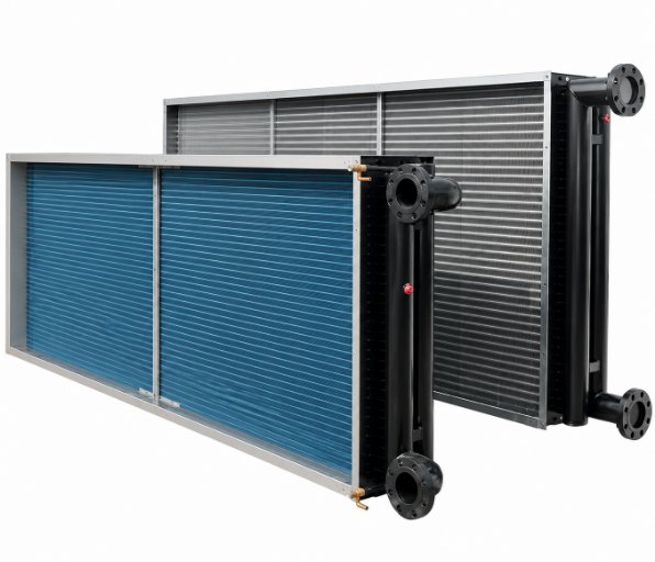
Koven Air designs custom dry cooling coils that provide sensible-only cooling – meaning no dehumidification, no condensate, no dew-point risk to drain-pan bacteria – to semiconductor, pharmaceutical, and high-precision manufacturing cleanrooms that cannot tolerate even a slight temperature deviation.
Key Performance Parameters
±0.2°C
Temperature Stability (Chengdu Case)
55±5%
Relative Humidity Precision
14–18°C
High-Temp Chilled Water Compatible
39.2–79.6%
Potential Energy Savings, Decoupled System
2.4 MPa
Factory Pressure Test, 100% Units
ISO Class 1
Sizing Compatible Cleanroom Deployment
Cleanroom Condensation & Humidity Coupling — How a Dry Cooling Coil Solves It
Most air-cooling coils perform simultaneous heat and moisture removal. This dual operation is not desirable in a cleanroom; each dehumidification cycle disrupts the narrow humidity band required by the process, and running a cooling coil below the room’s dew point risks condensation and contamination.
Sensible-Only by Design
A dry cooling coil (DCC) is built to do one job — sensible heat removal. Air moves across the finned coil face at roughly 23°C and leaves at a controlled lower temperature while its absolute moisture content stays unchanged, because the coil surface is sized to remain above the air’s dew point throughout the process. As a heat exchanger performing sensible-only heat exchange, a DCC differs from a conventional cooling system in exactly one respect: it delivers dry air without altering indoor air humidity.
Each DCC is sized against the simplified sensible-heat equation Qₛ ≈ 1.2 × V × (t₁−t₂), where V is airflow in m³/s and (t₁−t₂) is the entering-to-leaving dry-bulb temperature drop. Because the coil never crosses the dew point under normal design conditions, the sensible heat ratio (SHR) of a properly sized DCC approaches 1 — nearly all of the cooling capacity goes to temperature control, not moisture removal.
STANDARD
Cleanroom classification context: ISO 14644-1:2015.
That dry-surface operation is what allows a DCC to run on 14–18°C chilled water instead of the 6–7°C loop a standard cooling coil needs. The higher supply temperature raises chiller COP, extends the hours a site can run on free cooling, and removes the “overcool-then-reheat” energy penalty common in coupled systems.
- No condensate, no drain-pan bacteria risk — the coil surface stays dry across the operating envelope
- Compatible with high-temperature chilled water — 14–18°C vs. 6–7°C for standard cooling coils
- Pairs with independent humidity control — a make-up air unit (MAU) or desiccant wheel handles latent load separately, so the DCC can be sized purely for temperature
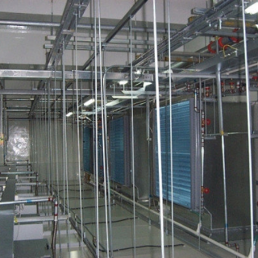
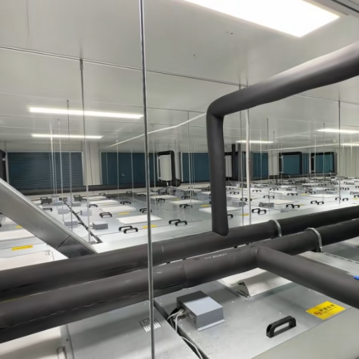
Condensation risk is not eliminated in every possible scenario. If ambient humidity spikes beyond design conditions, or pipe insulation is incomplete, a dry coil can still sweat. Koven Air’s KDC series offers an optional galvanized or stainless-steel drain pan (Drain Pan code G/S in the model designation) as a design safeguard for sites that want that margin, even though it is not required for standard-envelope operation.
This is one way a dry cooling coil system can be incorporated into a building air distribution design called temperature and humidity independent control (THIC), which is gaining favor in semiconductor cleanrooms, lithium-battery dry rooms, data centers and other environments where sensible cooling load and temperature precision, rather than large-scale humidity control, are primary concerns.
Koven Air Dry Cooling Coil Product Line — Models & Selection
Every Koven Air DCC is custom-built to the project’s airflow, coil-face velocity, and water-temperature parameters — we do not stock a fixed catalog of sizes. Selection runs through purpose-built engineering software calibrated against our own coil performance and test data, with routing optimized for turbulent-flow heat transfer at chilled-water temperatures above 14°C.
Cleanroom Dry Cooling Coil
- Application Semiconductor, PCB, lithium-battery dry rooms
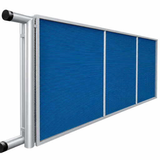
- Tube Hydrophilic aluminum-fin, copper or stainless tube
- Rows 2 or 3-row configurations
- Face velocity 1.5 / 2.0 / 2.5 m/s tested ranges
Sized against your FFU return-air path and cleanroom sensible-heat load, with routing tuned to keep face-velocity pressure drop within the FFU’s external static pressure budget.
Explore the Cleanroom Dry Cooling Coil →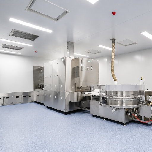
Pharma Process Dry Coil
- Application GMP production & packaging suites
- Tube Copper or stainless (contact-material options)
- Drain pan N / Galvanized / Stainless options
- Pressure test 2.4 MPa, 100% of units
Built for pharmaceutical suites where sensible-only cooling must coexist with strict environmental-control and material-contact requirements, with drain-pan and protective-mesh options selectable per line.
Explore the Pharma Process Dry Coil →KDC Model Designation — How to Read a Koven Air Coil Code
Every KDC unit carries a structured code (example: KDC-020-B-4-L-L-G-N-N-N) so engineers can verify a coil’s configuration without opening a spec sheet. Each position maps to a specific field, detailed below.
| Position | Field | Meaning / Options |
|---|---|---|
| 1 | Prefix | KDC — Koven Air Dry Cooling Coil |
| 2 | Size Code | Airflow class × 100 m³/h |
| 3 | Design Serial No. | Internal engineering revision |
| 4 | Copper Tube Spec | 3-3/8″ / 4-4/8″ / 5-5/8″ |
| 5 | Hand of Coil | L (left) / R (right) |
| 6 | Header Bend Direction | L / I (inlet-side) / O (outlet-side) / U (top) / B (bottom) |
| 7 | Drain Pan | N (none) / G (galvanized) / S (stainless) |
| 8 | Protective Mesh | N (none) / G (stainless mesh) |
| 9 | Flange | N (none) / F (flanged) |
| 10 | Pressure Holding | N (none) / P (pressure-hold shipping) |
At a 2.0 m/s face velocity and standard 23°C / 55% RH entering-air conditions, a 2-row coil handling 8,000 m³/h delivers approximately 7.8 kW of sensible cooling at 6.7 kPa water-side pressure drop; the equivalent 3-row configuration steps up to 11 kW at 16.9 kPa. Every dimension in that performance table is a starting reference — final coil geometry is recalculated for each project’s actual airflow, entering conditions, and available water temperature.
Performance-rating framework: AHRI Standard 410.
Dry Cooling Coil vs. Traditional Cooling Coils — Performance Comparison
A standard chilled-water cooling coil is designed to remove both sensible and latent heat, which means it runs cold enough to condense moisture on purpose. That works for a general air-conditioning zone, but it fights against a cleanroom’s independently controlled humidity system — every gallon of condensate the standard coil pulls out has to be replaced by the humidification system downstream.
| Dimension | Dry Cooling Coil (DCC) | Traditional Cooling Coil |
|---|---|---|
| Heat handled | Sensible only, SHR ≈ 1 | Sensible + latent |
| Chilled water temp. | 14–18°C | 6–7°C |
| Condensate / drain pan | Not required in normal design range | Required, continuous |
| Free-cooling window | Extended (higher supply temp.) | Limited |
| Best-fit deployment | Cleanroom, dry room, THIC systems | General comfort HVAC zones |
The dimension that matters most for a cleanroom operator is the chilled-water temperature line in that table. Running at 14–18°C instead of 6–7°C is not a marginal energy efficiency gain — it changes which refrigeration technology the plant needs and how many hours of natural cooling are available, directly cutting the energy consumption of the whole system.
Customer Results: ISO Class 1 Semiconductor Cleanroom Project in Chengdu
A semiconductor fabrication site in Chengdu needed an ISO Class 1 cleanroom across 4,954.95 m² of floor area — a two-story build with 4.8 m and 7.3 m clear heights and a total cleanroom volume of 59,459.4 m³. The environmental targets were unforgiving: 23±0.2°C dry-bulb, 55±5% relative humidity, a 13.1°C dew point, and +10 Pa positive pressure relative to outdoors.
4,954.95 m²
Total Floor Area
59,459.4 m³
Cleanroom Volume
23±0.2°C
Dry-Bulb Target
242 ACH
Calculated Air Changes/Hour
99.99995%
FFU Filtration Efficiency
40 Pa
Max. DCC Air-Side Pressure Drop
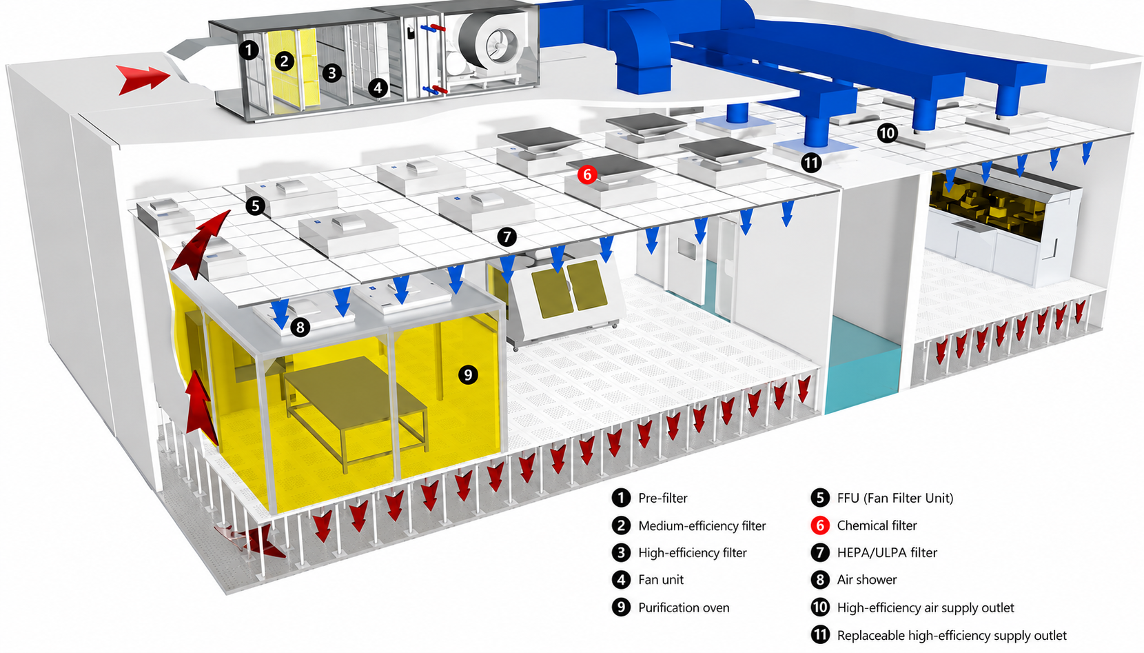
The system architecture paired three 50,000 m³/h MAU units (two duty, one standby) with Koven Air DCCs and ceiling-mounted FFUs — MAU handling deep fresh-air purification and humidity, DCC trimming return-air temperature, and FFU delivering uniform, filtered airflow into the cleanroom. Because the coils were selected against a hard constraint — 40 Pa maximum air-side pressure drop and 2 m/s maximum face velocity, set by the FFU’s available external static pressure — sizing had to balance heat-transfer area against airflow resistance rather than maximizing capacity alone.
Chilled-Water Control Architecture
The site runs a three-stage chilled-water control scheme: a constant-flow primary loop, a variable-flow secondary loop under variable-frequency pressure control, and a tertiary loop dedicated to the DCC valve group with bypass and balancing valves for precision temperature trim. Its secondary-to-tertiary mixing station blends the primary 6/12°C supply/return down to a 14/18°C DCC loop — deliberately staying above the 13.1°C room dew point to prevent condensation — with PID loops tuned over HART-protocol instrumentation.
The result, verified through on-site monitoring at a 5-meter equipment-height reference point, was a temperature field held within ±0.2°C of setpoint under a zoned closed-loop control strategy. That figure is a single project’s measured outcome, not a universal guarantee — but it demonstrates what the decoupled MAU-DCC-FFU architecture can achieve when sizing, control staging, and instrumentation are executed together rather than treated as separate purchases.
- Independent temperature, humidity, and cleanliness control loops — instead of one coil compromising on all three
- Electrically actuated water valves at the terminal, replacing duct reheat coils and removing the “overcool-then-reheat” energy loss common in coupled systems
- V-shaped and ring coil layouts used selectively to increase face area where straight-bank coils would exceed the 40 Pa pressure-drop budget
- Low-boron glass-fiber ultra-efficient FFU filtration to control airborne molecular contamination (AMC) at the wafer surface
Certifications & Compliance
Precision-cleanroom buyers evaluate a coil supplier on documentation as much as on hardware. Koven Air’s compliance position is deliberately specific rather than broad, because overstated certification claims are one of the fastest ways to lose trust with a technical procurement team.
- RoHS Copper tube material meets RoHS substance-restriction requirements
- ISO 14644-1 Sizing parameters designed to be compatible with cleanroom classification requirements
- AHRI 410 Rated per AHRI 410 sensible-coil test procedures
- GMP Equipment designed to support GMP environmental-control requirements
- 2.4 MPa Test 100% factory pressure-hold test, 3-minute hold, all units
ISO 14644-1:2015 defines cleanroom classes from Class 1 through Class 9 based on cumulative particle-count distribution across particle sizes from 0.1–5 μm. Each DCC’s airflow, face velocity, and pressure-drop parameters are sized against the target classification a project specifies — we describe this as “ISO 14644-1-compatible sizing,” not as an ISO-certified product, because classification certification applies to the completed cleanroom, not to an individual coil component.
AHRI 410, the industry rating standard for forced-circulation air-cooling and air-heating coils, explicitly covers sensible-only air-cooling coils alongside combined sensible-plus-latent coils in its test-procedure scope. Koven Air’s DCC line is rated per those AHRI 410 sensible-coil test procedures; we do not claim third-party AHRI certification, since that requires a formal certification program enrollment we have not pursued for this product line.
Every DCC ships only after a 100% factory air-tightness test at 2.4 MPa compressed-air pressure held for 3 minutes, with an optional nitrogen-pressurized shipping configuration available on request. Mechanical tube-expansion joins the copper tube to the aluminum fin pack to minimize contact thermal resistance, and header-bend routing is engineered to raise in-tube flow velocity and Reynolds number for stronger convective heat transfer at the higher 14–18°C water temperature this coil type is built to run on.
On the honest-limitation side: engineered “dry” operation reduces condensation risk under normal design conditions, but it does not physically make condensation impossible under every ambient scenario — see the Honest Limitation note earlier on this page for when an optional drain pan is worth specifying.
Procurement Guide: Selection, Lead Time & After-Sales Support
Because every Koven Air DCC is custom-engineered rather than pulled from a size chart, procurement is a three-stage process built around parameter verification rather than a fixed catalog checkout.
Our engineering team reviews your airflow, entering-air condition, target leaving-air temperature, available chilled-water temperature, and any FFU or ductwork pressure-drop constraint before a coil geometry is proposed. This step exists because a coil sized to generic assumptions — rather than your actual return-air path and pressure budget — is the most common cause of underperformance on cleanroom retrofits.
For projects retrofitting an existing MAU/FFU system, our team provides on-site guidance on coil orientation, header-bend direction, and valve-group placement so the new DCC integrates with the facility’s existing chilled-water routing rather than requiring a full mechanical-room rebuild.
Technical issues within the warranty period get a 24-hour response commitment, backed by lifetime free technical support and periodic training sessions for facility engineers and contractors on coil maintenance and control-loop tuning.
On Price and Lead Time
Because coil geometry, tube material, and drain-pan/mesh/flange options are all project-specific, exact price and lead time depend on your finalized parameters rather than a fixed price list. Cross-border buyers evaluating a Chinese HVAC supplier for semiconductor or pharmaceutical cleanroom work should expect a documented material-compliance and pressure-test data package as part of that quote — request one alongside your specification review.
That documentation requirement is not unusual. Independent industry reporting on cleanroom-equipment procurement notes that technical buyers in semiconductor and pharmaceutical projects routinely apply strict material-certification and compatibility-specification checks as a first-pass supplier filter, which is exactly why Koven Air leads with the pressure-test, material, and standards-compatibility data on this page rather than a general trust claim. For coil performance documentation, buyers can also request a rating basis aligned with AHRI Standard 410.
Frequently Asked Questions
What is the difference between sensible heat and latent heat in a cooling coil?
Sensible heat changes temperature; latent heat changes moisture content through condensation. A dry cooling coil handles sensible heat almost exclusively, keeping its SHR close to 1.
Why does a dry cooling coil need higher-temperature chilled water than a standard coil?
Keeping the coil surface above the air’s dew point is what prevents condensation, and that requires a warmer water supply — typically 14–18°C rather than the 6–7°C used in standard cooling coils that are designed to condense moisture on purpose.
Can a dry cooling coil be used in an ISO Class 1 cleanroom?
Yes — see the Chengdu ISO Class 1 semiconductor project referenced above.
Does a dry cooling coil ever need a drain pan?
Not under normal design conditions, since the coil surface stays above the dew point. Koven Air still offers an optional galvanized or stainless drain pan for sites that want additional protection against off-design humidity spikes or incomplete pipe insulation.
How is a cleanroom dry cooling coil sized differently for Class 1000 vs. Class 100 conditions?
Class 1000-type cleanrooms tend to carry a higher cooling load relative to airflow and need a larger temperature differential across the coil, while Class 100-type rooms run higher airflow against a lower load and need a smaller differential — which is why generic sizing rules of thumb do not transfer well between cleanroom classes and project-specific selection matters.
What tube materials are available for a dry cooling coil?
Two tube materials are available — copper and stainless steel — with hydrophilic aluminum fin as the standard fin material; material selection is typically driven by contact-material and corrosion-resistance requirements in pharmaceutical or high-purity applications.
Is a dry cooling coil the same thing as a dry cooler?
No, and the two terms get confused often enough to cause real procurement mistakes. A dry cooler is typically a closed-loop process-fluid heat rejection unit used in industrial or data-center cooling, sitting outdoors and rejecting heat to ambient air. A dry cooling coil (DCC) is a different category entirely — an air-side sensible-cooling component installed inside an HVAC air-handling path, cooling supply air rather than a closed process loop.
What data do I need to provide to get a DCC quote?
At a minimum, Koven Air’s pre-sale verification needs these project inputs:
- Design airflow rate
- Entering-air conditions: dry-bulb temperature and relative humidity, or wet-bulb temperature
- Required leaving-air dry-bulb temperature
- Available chilled-water supply and return temperatures
- Maximum allowable external static pressure for the FFU or downstream ductwork


![Commercial Rooftop Unit Guide: Types, Sizing & Costs [2026]](https://kovenair.com/wp-content/uploads/2026/07/commercial-rooftop-unit-guide-featured-2-150x150.png)