
Get in Touch with Koven Air Company


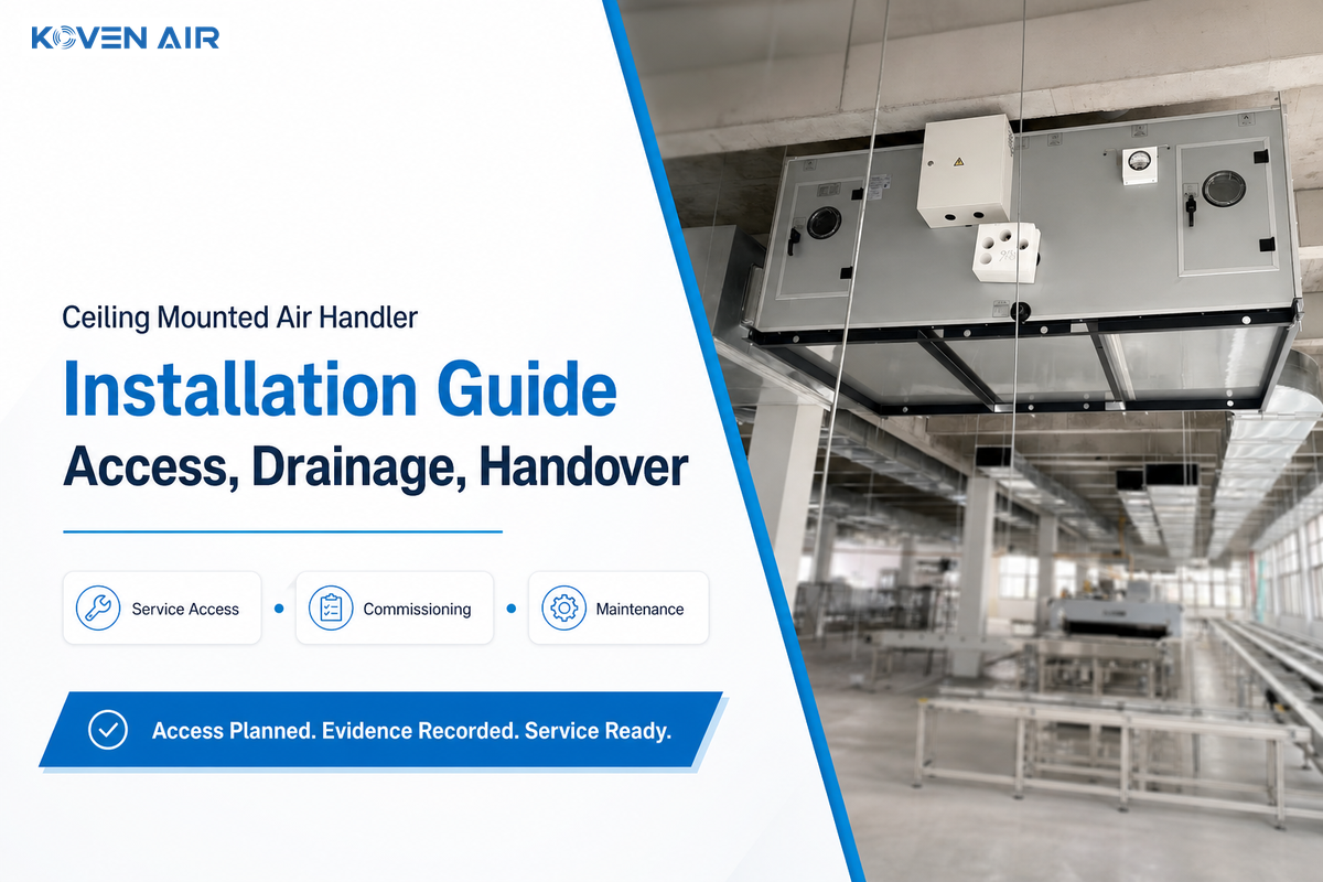
A ceiling mounted air handler is an indoor air-handling unit positioned in an overhead ceiling zone. It can free floor space, but it places service work, drainage, isolation, and access above the occupied zone. This guide is for commercial project teams that need a verifiable installation process and maintenance handover. It does not replace the unit manual, approved drawings, local code, or a qualified HVAC professional.
Quick project checks
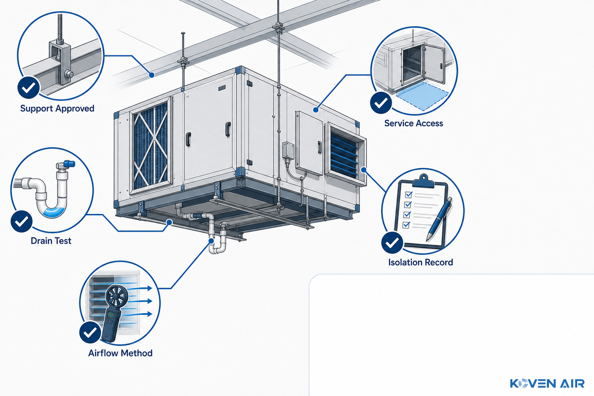
- Verify the mounting and support detail have been approved prior to delivery.
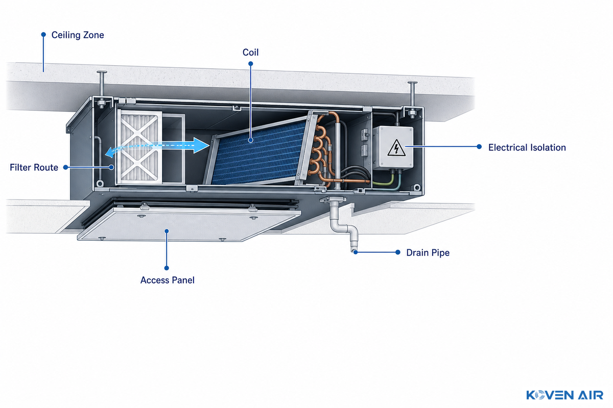
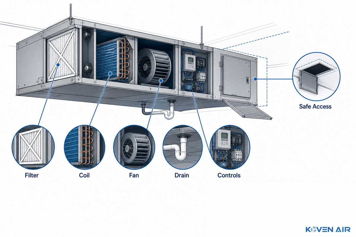
- Keep all air filter, coil, fan cabinet, drain, and control components accessible after ceiling closure.
- Record the drain test, air flow test method, control sequence, and energy-isolation procedure at handover.
Where the route includes electrical equipment, make the access and working-space review part of the task plan; OSHA electrical requirements provide the regulatory context. Its cited entrance provision uses 24 inches by 6.5 feet, also stated as 610 mm by 1.98 m, where that provision applies; the adopted local code and approved design govern the project detail.
Where this guide fits, and where the equipment page begins
The guide covers pre-installation checks, lifting, duct and pipe interfaces, wiring, commissioning steps, and routine maintenance. It gives commercial project teams a practical sequence for verifying access, interfaces, evidence, and handover. It is a field-execution guide, not a selection page.
Questions on capacity, chilled-water arrangement, discharge design, filter class, or project-specific configurations belong in an equipment review. See Koven Air ceiling mounted air handler solutions for that scope.
What changes when an air handler is installed above the ceiling?
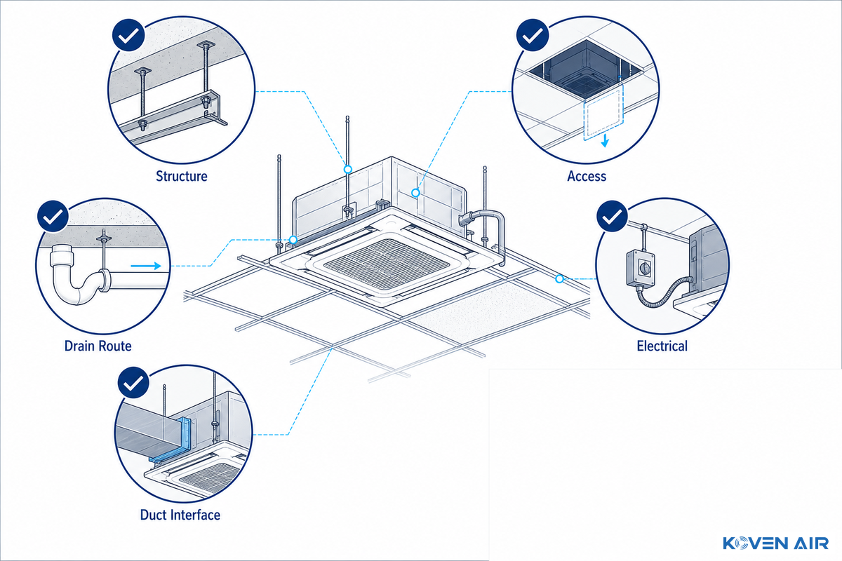
An indoor unit in the ceiling may be out of sight, but it cannot be out of reach. Installing air-handling equipment in that position changes the work sequence: confirm support and access before checking ducts, electrical circuits, controls, and condensate piping.
Technicians must be able to isolate the system, open the cabinet, inspect the coil, remove a filter, clean accessible surfaces, and restore the ceiling safely. For electrical portions of that route, OSHA’s electrical-equipment access rules are a useful regulatory reference. A drawing that omits these routes is not a maintenance plan.
The 5-Check Ceiling Readiness Screen before delivery
| Check type | Evidence to collect | Project owner |
|---|---|---|
| Structure | Approved support and vibration-isolation detail | Project engineer |
| Mounting route | Lifting plan, opening, and delivery path | Mechanical contractor |
| Access | Panel, tool, lift, and technician-clearance route | Facilities lead |
| Drainage | Pipe route, trap detail, test point, and safe overflow path | Mechanical contractor |
| Electrical | Disconnect, wiring diagram, and control interface | Electrical contractor |
| Ductwork | Supply and return connections plus test points | Sheet-metal contractor |
| Start-up | Commissioning record and defect-closeout route | Commissioning team |
| Documents | Unit manual, approved submittal, and task procedure | Project manager |
| Handover | Operator briefing and escalation contact | Facilities lead |
Before opening a cabinet or disturbing electrical, pneumatic, hydraulic, or other energy sources, the team needs a site-specific energy-control procedure. OSHA 29 CFR 1910.147 addresses general-industry servicing and maintenance through an energy-control program that prevents unexpected energization, start-up, or stored-energy release. Installation, alteration, and construction work can fall under different applicable rules. Actual isolating devices and the verification step must align with the installed system and task; a warning label is not sufficient isolation.
Turn mounting, lifting, and access into one work package
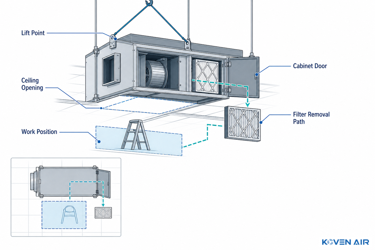
Mounting is more than a support detail. It is the first step in a service route that continues through the ceiling opening, access panel, work position, cabinet door, and component-removal path. Before finishes conceal the equipment, ask the contractor to demonstrate how a qualified professional will approach the unit with tools, remove the air filter, inspect the coil, and reach the control enclosure. OSHA’s rules on access to electrical equipment reinforce why the route and work position should be resolved before handover. Include lifting restrictions, shutdown dependencies, and access-panel limitations in the operations documentation.
Field tip: Treat each service task as a physical route: isolate, approach, open, inspect, remove, reinstall, verify, and restore. If one part of that route lacks safe clearance, resolve it before handover instead of leaving a future repair to dismantle finished work.
Use the access proof, not the panel-size assumption
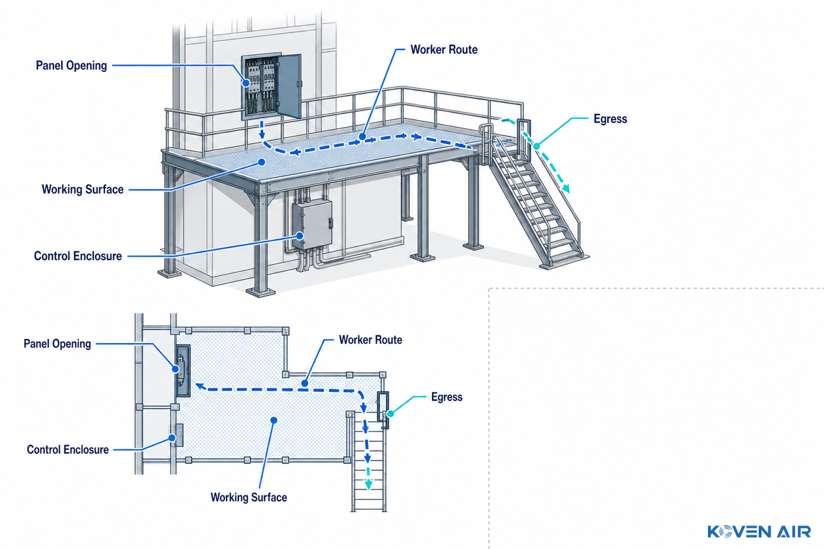
An access panel shows that an opening exists, not that the work can be performed through it. A common failure is to accept a panel that lets someone see the air handler but not remove a filter, clean a coil, repair a control, or reach a drain connection. A full access proof considers the worker route, working surface, egress, lighting, and any required lifting equipment. For the dry run before ceiling close-out, use the actual panel location and access equipment; pay particular attention when ductwork, water pipes, cable trays, or structural members share the overhead zone.
Code examples are not universal project dimensions: use the version adopted by the authority having jurisdiction and the task-specific electrical and mechanical requirements.
| Reference type | Example provision | Project use |
|---|---|---|
| 2018 IMC 306.1 | 30 inches deep by 30 inches wide: 762 mm by 762 mm, or 0.762 m by 0.762 m, at the control side | Confirm the adopted-code requirement before finalizing service access. |
| OSHA 1910.303 | Electrical-work-space entrance example: 24 inches wide by 6.5 feet high, also stated as 610 mm by 1.98 m | Check electrical-service access against the applicable task and equipment. |
| OSHA 1910.303 | 30 inches, or 762 mm, of rear working space where rear access is required; the source also identifies a 1.83 m panel-width condition and distinct 600 V contexts | Do not place unrelated pipes or ducts where they obstruct the required work area. |
| 2024 IMC 307.2.1 | Condensate example: 1% slope, equivalent to 3.175 mm per 304.8 mm horizontal run | Use only where this adopted-code provision applies; the unit manual and local requirements still govern the installation. |
Condensate drainage is a commissioning item, not a finishing detail
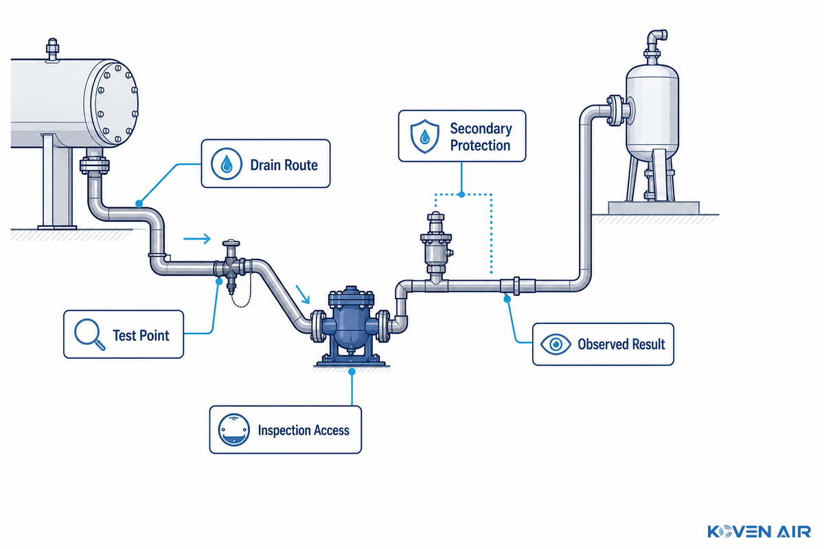
Drain failures often occur post-ceiling closure. Drain configuration, trap material, slope, cleanout, and secondary protection are dictated by the unit manual, approved design and local mechanical requirements. The U.S. Department of Energy’s HVAC commissioning overview supports using documented verification rather than assumption. During commissioning, run the unit to match project procedure requirements, check the drain route, and note where a result was observed.
Don’t import a drain detail from another air handler size and type without comparing against the manual and system conditions.
A handover note should identify the primary drain path, secondary protection where provided, the point where blockage can be detected, and the safe technician-access route. This record helps the owner distinguish an ordinary inspection from a repair that requires ceiling access or system shutdown.
Connect ducts, wiring, and controls to a measurable handover plan
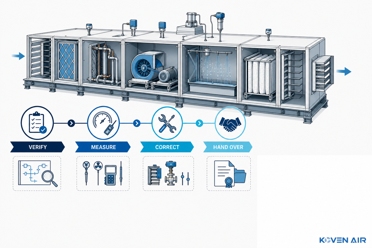
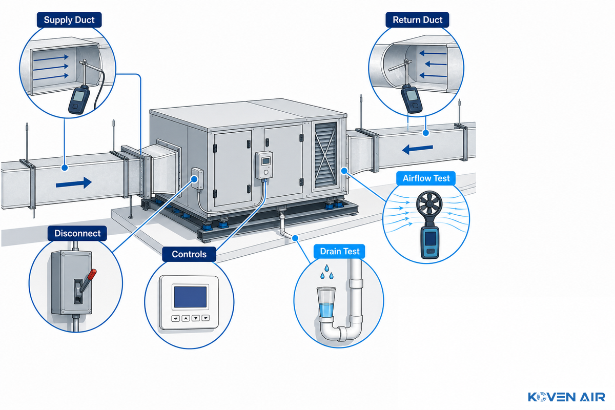
Connections must be proven, not merely documented. Record the supply and return duct path, electrical disconnect, wiring and control points, the measured air-flow method, temperatures, and the drain-test result. ASHRAE commissioning guidance frames the work around verifying and documenting that systems meet owner project requirements; the U.S. Department of Energy’s HVAC commissioning overview offers a public-sector reference for that process. As a result, the document should be a testable record for the facilities team, not a generic start-up checklist.
Use the 4-Stage Overhead AHU Commissioning Record
- Prove installed connections, access panels, safety devices, and the final equipment position against project documentation.
- Measure the air flow, temperatures, electrical readings, control response, and condensate test using the project method.
- Repair any accessible defects before ceiling or finishes cover repair access or make costly repairs a disruptive task.
- Hand over the unit manual, isolation procedure, test record, and planned service route to the operator.
The U.S. Department of Energy’s HVAC commissioning overview supports this evidence-led handover approach; the exact tests and acceptance criteria remain project- and equipment-specific.
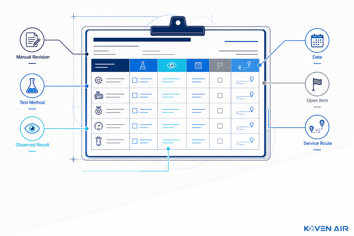
Handover record: Keep the approved manual revision, final equipment position, access-panel location, test method, observed result, date, and unresolved item together. Note who accepts the record and where it will be stored. The next qualified technician can then verify the previous condition without guessing which drawings, procedures, or readings were current at handover.
Build a maintenance routine around condition, access, and compliance
Maintenance should reflect operating hours, contamination load, water quality, heating and cooling duty, and the manufacturer manual rather than an arbitrary schedule. Set regular review intervals that the facilities team can adjust when operating conditions change. ASHRAE Standard 180 resources provide a commercial-building maintenance framework, while the approved procedure defines the actual task. Begin with visual inspection and access checks, then proceed with filters, coils, fans, drains, and controls. Remove dirt and debris only when the task is safe and the method is approved. Qualified technicians should perform electrical, refrigerant, water-system, and repair work.
| Maintenance task | Access proof | Record to retain |
|---|---|---|
| Filter inspection or replacement | Filter withdrawal route is clear | Condition, action, and replacement reference |
| Coil inspection or cleaning | Cabinet and coil face are reachable | Method, condition, and follow-up need |
| Fan and cabinet inspection | Energy isolation and panel route are confirmed | Observed condition and corrective action |
| Drain check | Test point and pipe route can be reached | Test result and any escalation |
| Controls service | Control enclosure and wiring are accessible | Setpoint, sequence, and verification result |
When an installation question becomes an equipment question
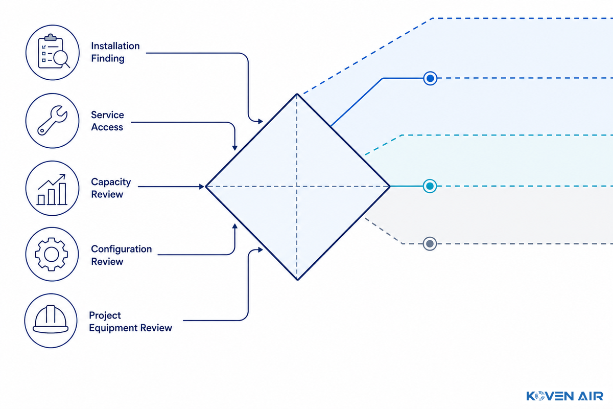
Use this guide to document installation and service findings. If the project concern shifts to capacity, cooling or warm-air duty, application environment, cabinet configuration, or other performance decisions, return to the project system documentation. Do not use it as a residential do-it-yourself guide.
To install an air handler during the installation of air-handling equipment, use a step-by-step work package and attach the approved manual. Proper air flow and airflow, cold-air delivery, comfort, and blower performance depend on the complete HVAC system, not a single checklist. Outdoor piping or refrigerant vacuum work on the HVAC system requires qualified technicians and the manufacturer system instructions. For service tasks involving hazardous energy, use the site’s task-specific procedure and the regulatory context in OSHA 1910.147. For configuration, capacity, or application questions, move to the project-specific equipment review rather than extending this installation guide. That boundary supports industry best practice and lets teams work efficiently without turning a maintenance guide into a generic HVAC system product entry.
FAQ
What is the most critical safety precaution during maintenance?
Begin by identifying every hazardous energy source associated with the task. Apply the site-specific energy-control procedure whenever unexpected start-up or stored energy could cause injury, and verify isolation before service begins. Write the procedure for the installed equipment and the task, not from an online checklist. If the access route cannot be performed safely after isolation, stop and correct the access problem before work continues.
Why does duct sizing matter in a ceiling installation?
Ductwork affects air flow, noise, static pressure, and whether the fan can deliver its intended operating point. Compare the duct connection with approved design documents and manufacturer data. Record the measurement method instead of inferring air flow from a nameplate.
Why use a secondary drain pan or protection?
Secondary protection is an application- and code-dependent safeguard where an overflow could damage occupied space. Unit manuals and local requirements govern the arrangement. Include the primary drain test, the alarm or visual indication of an overflow, and the owner first-response action in the handover documents.
This is more useful than assuming the same drain geometry works in every HVAC system. The record should also name the person who receives the alarm, the safe first action, and the access point a technician will use to investigate before water reaches finished ceilings or electrical equipment.


![Commercial Rooftop Unit Guide: Types, Sizing & Costs [2026]](https://kovenair.com/wp-content/uploads/2026/07/commercial-rooftop-unit-guide-featured-2-150x150.png)