Get in Touch with Koven Air Company

Air-to-Water Heat Pump: A Practical Hydronic Systems Guide


Updated: October 9, 2026
An Air-to-Water Heat Pump is a hydronic system that takes heat from outdoor air and delivers it to a water circuit. The technology is simple, but the project decisions are not. Useful results depend on the building load, required water temperature, emitter output, minimum flow, part-load behavior, freeze strategy, controls, commissioning, and local rules.
This guide explains how those project decisions are related to one another. It is factual support content for the engineers, owners, specifiers, and procurement teams writing the hydronic project brief. Equipment models, capacity ranges, configurations, price, quotation, lead time, and RFQ intent remain on Koven Air’s air-to-water heat pump solution page. Broad comparisons across industrial and commercial heat-pump families remain in the industrial and commercial heat pumps guide.
Quick specs for this guide
- System boundary: outdoor refrigerant circuit plus hydronic distribution and controls
- Five design inputs: load, water temperature, emitter output, hydraulic limits and operating envelope
- Key evidence: condition-specific capacity, minimum output, flow, temperatures, electrical input, and control response.
- Not covered: model selection, price quotations, and buying terms
BLUF
Start with the heat load and the lowest practical water temperature. Prove emitter output, hydraulic stability, cold-weather capacity, minimum turn-down, and control ownership at stated conditions. Select equipment only after those boundaries are recorded.
What an Air-to-Water Heat Pump Connects
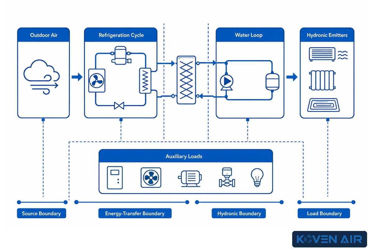
Air-to-water equipment connects two changing systems. One is an outdoor-air refrigeration cycle, and the other is an indoor water loop. Outdoor temperature changes the available source heat, while load, emitters, flow, and setpoints change the water-side demand. Projects succeed when both sides remain compatible across design-day, part-load, defrost, and mode-change conditions.
In practice, the project checks whether both sides remain compatible in a retrofit application across design-day and part-load conditions, because a rating-point mismatch can hide pumps, backup heat, or emitters.
The outdoor unit absorbs heat from ambient air and raises refrigerant pressure and temperature through compression. The heat exchanger then transfers that energy to water. Pumps then move heated water to radiant floors, radiators, fan coils, air-handler coils, storage, or a domestic-hot-water interface. Reversible systems may also produce chilled water. Cooling then requires humidity and condensation controls that heating alone does not require.
System boundaries are important when considering ratings. COP of equipment may describe the heat-pump package at one test point. Installed electricity may also include distribution pumps, crankcase or pan heaters, backup heat, and controls. Delivered heat may change during defrost or when a higher water-temperature request increases compressor lift. AHRI’s Standards Overview elaborates on why a rating must be in exact alignment with the test point and system boundary.
Project briefs should avoid statements like “the unit works down to a certain outdoor temperature” without stating what useful capacity, leaving water temperature, defrost behavior and electrical input applies to that statement. An operating limit shows that the machinery can work. It does not prove that the system can serve the building at that point.
A well-defined heat pump system can be efficient at space heating and water heating when the temperature lift, distribution losses, auxiliary loads, and operating hours are stated. The phrase “efficient” is incomplete without the aforementioned limits.
Separate Search Vocabulary from Design Evidence
Search results mix adjacent technologies and audiences. A homeowner may ask how a heat pump works, whether a water heat pump works like a water heater, or whether one unit can provide heating and cooling. In an HVAC project, air heat describes the source while hydronic heat describes water-side delivery; neither phrase proves capacity. An air-to-air heat pump, mini-split, ductless system, ducted unit, SpacePak small-duct system, and air-to-water machine distribute energy differently. Brand searches for Daikin or LG, and a phrase such as boiler company, do not replace a condition-specific design brief.
Emitter and equipment searches add more labels: underfloor heating, radiators or baseboards, heat pump units, monobloc design, electric heat, and a heating system used to heat domestic hot water. A monobloc design may place water outside; that boundary matters when outside air falls on the coldest days or when water piping carries heat through air in the winter. The project still needs measured heating needs, emitter output, minimum flow, and a documented installer setup.
Commercial claims also need boundaries. Reliability, a seal around the living space, energy savings, energy efficient operation, lower emission, electrification, and an eco-friendly or cost-effective result depend on the load and operating record. A plan to convert fossil heat must state how electric resistance backup is controlled. These terms help an owner or homeowner frame questions, but they cannot show that one unit will meet every condition.
Use the Five-Input Hydronic Fit Check Before Product Selection
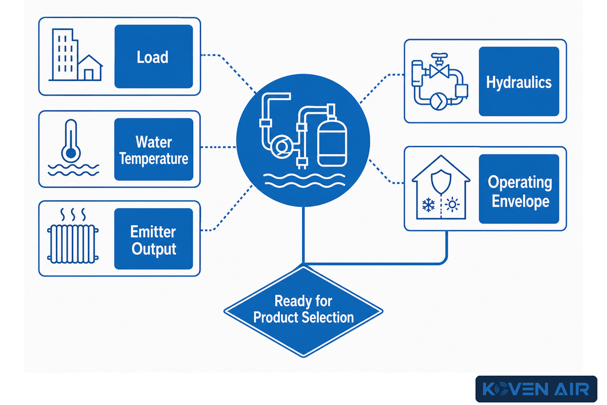
The Five-Input Hydronic Fit Check turns a vague replacement request into a testable design basis. Each input contains a required record and a failure question. If any input is left assumed, a model comparison is started too early because the project has not defined the duty the equipment must perform.
| Input | Evidence to record | Failure question |
|---|---|---|
| 1. Load | Room or zone load, design weather, load duration, schedules, and any planned envelope work | Was the legacy boiler size mistaken for the actual load? |
| 2. Water temperature | Outdoor-reset schedule, design supply and return temperatures, and mode-specific requests | Can the load be met at a lower temperature than the old setpoint? |
| 3. Emitter output | Room-by-room output at the proposed mean water and room temperatures | Which room fails first as water temperature falls? |
| 4. Hydraulics | Required and available flow, pressure loss, active volume, zoning states, pump authority, and water quality | Can every allowed zone state preserve minimum flow and stable run time? |
| 5. Operating envelope | Maximum and minimum output, ambient and water conditions, defrost, backup, mode priorities, and electrical limits | Can the system cover peaks without cycling through common low-load hours? |
Of the five inputs, load comes first in the design process because oversizing impacts both capital cost and operation. Design loads require analysis to ensure equipment is sized for the maximum load, while a load-duration view shows how many hours occur at smaller loads. The US Department of Energy sizing guide states that minimum capacity matters alongside maximum capacity and links inadequate turn-down with cycling. These air-to-water heat pump principles apply to part-load behavior, but product-specific ratios should not be transferred.
Water temperature is the link between load and equipment. Lowering it can reduce temperature lift, but only if emitters still deliver enough heat. If emitters deliver sufficient heat, the hydraulic design must still keep the heat exchanger within allowable flow limits as other zones open and close. The operating envelope joins design-day capacity checks with defrost, backup, electrical service, mode changes, and shoulder-season cycling.
Decision rule: do not move from feasibility to product selection until every input has an owner, a data source, a design value or schedule, and an acceptance test.
Match Water Temperature to Emitter Output, Not Emitter Age
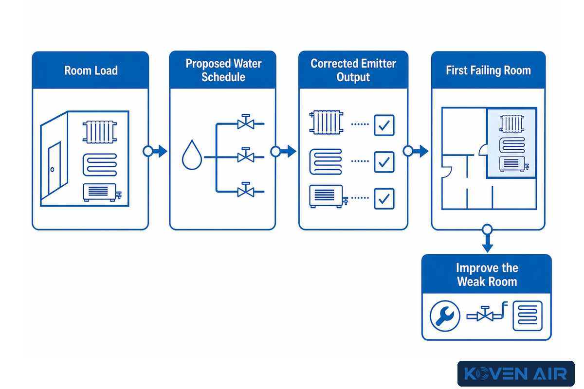
Emitter compatibility is an output question rather than an age label. Existing radiators, baseboards, radiant floors, fan coils, and air-handler coils can only be accepted after their output is checked at the proposed water schedule and room condition. Lowering water temperature can be valuable, but comfort still depends on heat.
The Massachusetts Clean Energy Center notes that existing radiators and baseboards may need changes because heat-pump hot water can be cooler than boiler water. That warning is a starting point, not a verdict on every old emitter. Oversized radiators may work well at a reduced temperature; a newer but undersized panel may not.
| Emitter type or load | Compatibility question | Evidence before acceptance |
|---|---|---|
| Radiant slab | Can the floor surface and circuit spacing meet load safely? | Loop drawing, floor build-up, room load, flow, and surface limit |
| Thin radiant panel | Does lower mass change control and cycling behavior? | Panel data, active area, flow, control deadband, and load profile |
| Low-temperature panel radiator | Is certified output available at the proposed mean water temperature? | Output correction data and room-by-room selection |
| Oversized legacy radiator | Does excess area offset the lower temperature? | Measured dimensions, construction, output table, and room load |
| Standard legacy radiator | Which design hours require more output? | Corrected output plus weather-based room load |
| Baseboard or convector | Does output fall too far at the lower temperature? | Element length, enclosure condition, flow, and correction data |
| Trench convector | Are natural or fan-assisted ratings applicable? | Fan state, grille condition, water schedule, and output data |
| Hydronic fan coil | Can water flow and fan speed meet heat and sound targets? | Coil map, fan curve, sound data, condensate provision, and controls |
| Air-handler coil | Can the coil meet sensible and ventilation loads at design airflow? | Coil selection, airflow, air temperatures, water flow, and pressure loss |
| Indirect DHW coil | Is coil area adequate at the heat-pump water temperature? | Coil rating, tank volume, draw profile, recovery target, and hygiene cycle |
A practical retrofit sequence is to calculate each room load, record the installed emitter, correct its output to the proposed mean water temperature, and identify the first room that fails. Envelope work, increasing the area of the emitter, a fan-assisted terminal unit, flow correction, or a revised temperature schedule may be used to improve the room. Raising the entire system temperature to solve one weak room can penalize every operating hour.
Evaluating chilled floors and chilled panels requires a distinct check. Chilled surfaces can fall below room dew point and collect moisture, even if cooling capacity seems adequate. Official ASHRAE materials support dew-point-aware supply conditions and identify dehumidification responsibility. A radiant cooling design should name a humidity sensor, safety margin, water-temperature reset, latent-load system, ventilation path, and lockout response.
Monobloc or Split: Locate the Freeze Boundary First
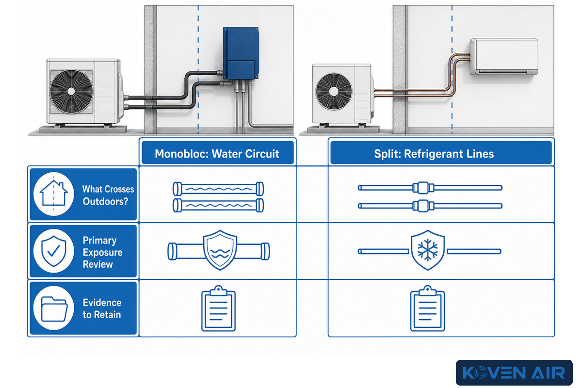
Monobloc and split describe where the refrigerant-to-water interface sits. The first decision is where to place the boundary between outdoors and indoors and whether refrigerant or water crosses it. Installation capability, freeze exposure, service practice, code, and site layout then shape the choice.
An official US Federal Register document describes the physical distinction: a split arrangement connects outdoor equipment to an indoor hydrobox with refrigerant piping, while a monobloc arrangement contains the refrigeration circuit outdoors and sends water piping indoors. Project terminology can vary. In such cases, piping diagrams are more reliable than labels.
| Boundary question | Monobloc implication | Split implication |
|---|---|---|
| What crosses outdoors? | Water or water-antifreeze circuit | Refrigerant lines between outdoor and indoor sections |
| Primary exposure review | Freeze, pump outage, pipe route, fluid properties, drains, alarms | Refrigerant installation, charge, leak, code, and qualified service |
| Evidence to retain | Exposure temperature, fluid plan, pressure loss, power-loss response | Line sizing, length/elevation limits, pressure test, evacuation, charge record |
No single protection method or glycol concentration satisfies all projects. Heat capacity, viscosity, pump duty, materials, and other service factors must be balanced against code and maintenance practice. Measures used to protect equipment against freezing (e.g. heat trace, drain-down, backup circulation, enclosure, alarms, and antifreeze) can be selected in layers based on code and failure analysis. Record the lowest credible exposure, outage duration, protection objective, fluid concentration or alternate method, verification test, and maintenance owner.
Decide on Buffers, Pumps, and Zoning from Functions
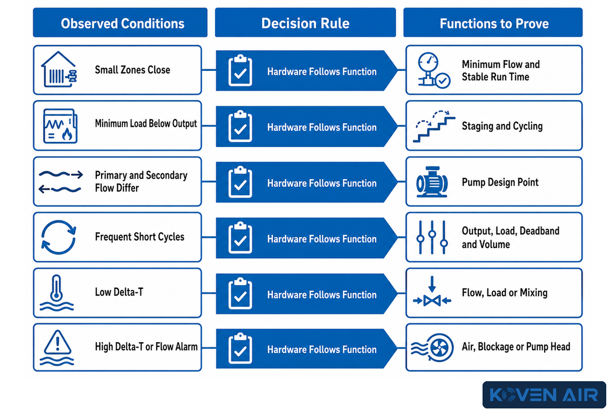
Hydronic hardware should solve named flow, volume, separation, storage, air-removal, and control functions. A buffer tank is not a default badge of good design, and a hydraulic separator is not free insurance. The correct arrangement preserves equipment limits while allowing the distribution system to respond to changing zones without hiding faults.
| Observed condition | Question before adding hardware | Possible response to evaluate |
|---|---|---|
| Many small zones close | Can the remaining circuit keep minimum unit flow? | Open reference zone, bypass, variable pumping, header, or separation |
| Minimum load is below unit output | Can staging or zoning reduce cycling without storage? | Smaller stage, more active volume, schedule change, or buffer |
| Primary and secondary flows differ | Does either pump disturb the other’s design point? | Low-loss header, closely spaced tees, or functional buffer connection |
| Large temperature swing | Is the sensor seeing load temperature or mixed tank temperature? | Sensor relocation, piping correction, control rewrite, or volume change |
| Frequent short cycles | Are minimum output, load, deadband, and active volume known? | Correct controls and flow first; size storage from a stated run-time basis |
| Low delta-T | Is flow excessive, load small, or mixing present? | Balance circuits, verify sensors, tune pumps, or correct bypass paths |
| High delta-T or flow alarm | Is there air, blockage, fouling, valve closure, or inadequate pump head? | Purge, clean, balance, correct valve logic, or recheck pump selection |
| Two temperatures are required | Can reset and mixing serve both without raising all production? | Separate circuit, mixing control, priority period, or emitter change |
| Buffer plus separator proposed | Are both devices performing distinct, documented functions? | Combine functions where the piping and controls allow |
A 2025 Plumbing & Mechanical hydronics case indicates that buffer storage and hydraulic separation can perform the same functions in some arrangements. This case doesn’t remove buffers. It allows a better question: which function is needed, what zone, and what flow state, and where is the controlling sensor?
Three operating sketches are helpful before the piping is finalized: every zone open at design load, the smallest permitted zone in mild weather, and a mode transition such as domestic-hot-water priority or defrost recovery. For each, determine flow and active volume, mixed temperature, pump state and direction, and sensor response. Good design explains these states without an operator holding a valve in a desired position.
Check Cold Weather, Defrost, Backup, and Turn-Down Together
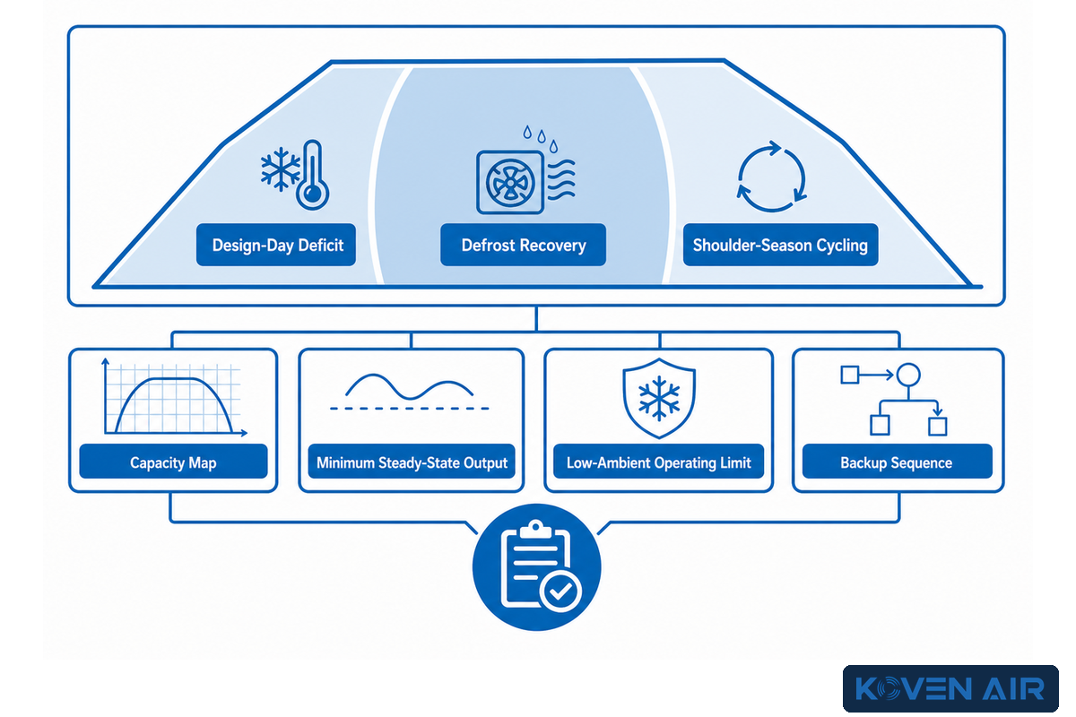
Cold-weather suitability is a joined sequence, not one minimum ambient number. The review connects the useful capacity at temperature, the building load, defrost behavior, backup staging, electrical constraints, and output during mild conditions. Peak shortage and part-load cycling are different risks and require different evidence. DOE sizing guidance treats peak shortage and part-load cycling as different risks, so this review records both maximum capacity and minimum turn-down evidence.
Scenario 1, design-day deficit: published unit capacity is lower than the calculated load at the site’s design outdoor condition and required leaving-water temperature. Options to address this scenario include reducing the load, lowering water temperature, or increasing unit capacity. Defining staged backup is also an option. Claiming that the compressor can still operate at a colder temperature will not close the capacity gap.
Scenario 2 – Defrost recovery: The unit’s operation is temporarily reversed to address frost buildup on the coils. The water loop absorbs the event without unacceptable space or supply temperature disturbance. The brief should include usable water volume, backup behavior, emitter response, drain path, sensor sequence, and how the event will be observed during commissioning.
Scenario 3, shoulder-season cycling: design-day capacity is adequate, but the building often needs less heat than the unit’s minimum stable output. A closed zone, narrow deadband, or high minimum compressor capacity allows the unit to cycle more frequently and reduces stable run time. Record minimum output at relevant conditions, the smallest active load, usable system volume, staging, and control deadband. Address staging and control behavior before adding a tank by habit.
| Cold-weather evidence | What it proves | What it does not prove alone |
|---|---|---|
| Capacity map in kW | Available output at named outdoor and water conditions | Building load, defrost impact, or pump energy |
| Minimum steady-state output | Turn-down at a named condition without cycling off | Stable operation with the planned zones and volume |
| Low-ambient operating limit | A permitted operating boundary | Useful output or efficiency at that boundary |
| Backup sequence | How unmet load, faults, or recovery are handled | Whether backup is hidden during normal operation |
Ownership of balance-point logic is required. Outdoor temperature alone may not be sufficient. Loads, delivered water temperature, limits of the compressor, tariff, demand, and recovery time may also be considered. Trend compressor demand, backup demand, temperatures, zone calls, defrost state, and alarm state to avoid unnecessary backup.
Coordinate Heating, Cooling, and Domestic Hot Water
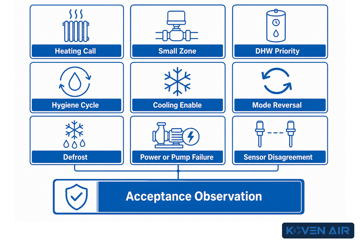
Multiple modes ask the same equipment for different temperatures, flows, and priorities. Space heating may prefer low-water temperature, domestic hot water may need a hotter cycle, and cooling may need dew point protection. A stable design assigns each valve, pump, sensor, setpoint, interlock, and fallback to one clear sequence.
| Mode event | Control question | Acceptance observation |
|---|---|---|
| Heating call begins | Which load and outdoor condition set the target? | Reset target, flow proof, pump state, valve state, and stable start |
| Small zone remains | How are minimum flow and run time protected? | Actual flow, compressor modulation, cycle length, and bypass state |
| DHW priority starts | Which space load pauses and for how long? | Valve proof, tank sensor response, recovery time, and heating recovery |
| Hygiene cycle starts | Which heat source, limit, mixing protection, and record apply? | Stored-water and outlet protection records under local requirements |
| Cooling enable | Who owns latent load and dew-point calculation? | Humidity, dew point, water target, lockout, and condensate path |
| Mode reversal | How is residual hot or cold water isolated? | Valve timing, mixed temperature, pump delay, and terminal response |
| Defrost occurs | Which loop volume and backup response support recovery? | Temperatures, power, valve state, duration, and recovery trend |
| Power or pump fails | How is freeze exposure reduced and alarmed? | Fail position, alarm delivery, backup source, and restart sequence |
| Sensor disagrees | Which value is trusted and what safe state follows? | Cross-check, fault threshold, alarm, fallback, and service record |
Potable hot water needs a water-safety plan separate from space-heating efficiency. Current US CDC guidance recommends storing hot water above 60°C, keeping circulating hot water above 49°C, and following anti-scald rules. Those values are US public-health guidance rather than a universal equipment setpoint. Local code, water-management requirements, storage design, mixing protection, occupant risk, and the actual heat source must govern the final sequence.
Commission, Maintain, and Troubleshoot with Measurements
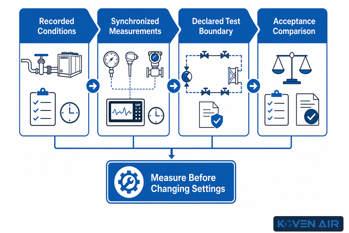
To prove the stated function, commissioning should capture recorded conditions, not just confirm compressor startup. Water flow, entering and leaving temperatures, electrical input, and control response can be part of a proof test set. Whether or not these readings mean anything is determined by how accurately the sensors measure, when and how timestamps are synchronous, and what the test boundary is.
“Quality installation and commissioning are critical to optimizing heat pump performance.”
PNNL’s detailed installation page is primarily air-side. A separate PNNL water-loop O&M source covers temperature, pressure, flow, and electrical measurements for comparison with manufacturer information, but it focuses on ground-source equipment. The measurement logic is useful here, and the four-point air-to-water record below is an article-level project framework rather than a universal PNNL checklist.
Illustrative operating snapshot
The following numbers represent one hypothetical calculation record and are by no means product data, design targets, or acceptance limits. These numbers are to demonstrate how units and conditions must be captured in a single timestamped set. In a real project, every number must be changed to design information and measured data.
| Measurement category | Hypothetical recorded values | Reason for pairing |
|---|---|---|
| Weather and room | Outdoor 2°C; room 21°C | Fixes source and load context |
| Humidity boundary | 45% RH; calculated dew point 8.6°C | Supports cooling lockout review |
| Primary water temperatures | Leaving 40°C; entering 35°C | Establishes a 5°C measured difference |
| Water flow and heat | Flow 0.50 L/s; calculated transfer 10.5 kW | Joins flow and temperature difference |
| Electrical boundary | Package 3.8 kW; distribution pump 0.18 kW; backup 0 kW | Prevents hidden auxiliary energy |
| Part-load state | Active-zone load 3.2 kW; minimum unit output 2.5 kW | Tests turn-down margin |
| Run behavior | Steady run 45 min; 1 start/h | Shows cycling and observation duration |
| Hydraulic pressure | Static 210 kPa; pump differential 35 kPa | Supports pump and blockage checks |
| DHW recovery | Tank 300 L; observed recovery 75 min | Connects storage to a timed duty |
| Radiant heating loop | Supply 32°C; return 28°C | Separates mixed-loop conditions |
| Radiant cooling check | Water 16°C; room dew point 12°C; margin 4°C | Shows the required moisture context |
| Defrost event | Defrost 8 min; recovery 12 min | Makes recovery visible |
| Outage case | Power loss 4 h; assessed exposure -10°C | Links freeze analysis to a duration |
| Sensor cross-check | Reference 39.8°C vs sensor 40.0°C; reference 34.9°C vs sensor 35.0°C; meter 0.49 L/s vs display 0.50 L/s; meter 3.75 kW vs display 3.80 kW | Makes measurement agreement explicit |
| Proof item | Record together | Decision supported |
|---|---|---|
| Water flow | Meter method, units, pump speed, valve and zone state, fluid type | Heat-exchanger range, hydraulic stability, and pump condition |
| Water temperatures | Entering and leaving readings, sensor locations, calibration, target, outdoor condition | Temperature lift, emitter delivery, and calculated thermal transfer |
| Electrical input | Compressor, pumps, backup, heaters, voltage, current, and time interval | Energy boundary, hidden backup, and condition-specific performance |
| Control response | Calls, setpoints, valves, stages, alarms, timestamps, steady-state and transitions | Sequence compliance, cycling, mode priority, and fault handling |
Not every system has permanent instrumentation. Define what will be permanently trended and what a technician will measure during an acceptance test. What temporary sensors will be installed for seasonal testing? A design-day test may be impossible at handover; when it is deferred, record the required weather window, responsible party, expected trend set, acceptance band, and closeout date.
| Symptom | Measure before changing settings | Likely branch to test |
|---|---|---|
| Rooms cold at design weather | Room load, supply/return temperatures, flow, zone state, outdoor condition | Load, emitter output, water target, balance, or capacity |
| One room cold | Room temperature, emitter temperatures, flow or valve position, air presence | Local emitter, balance, valve, sensor, or envelope |
| Frequent starts | Minimum load, minimum output, active zones, volume, deadband, start count | Oversizing, controls, zoning, flow, or usable volume |
| High electricity use | Thermal output, compressor input, pump input, backup runtime, temperatures | Energy boundary, high lift, backup, defrost, or schedule |
| Flow alarm | Differential pressure, actual flow, valves, strainers, air, pump command | Blockage, air, pump, closed zones, sensor, or bypass |
| Low delta-T | Matched temperatures, flow, load, bypass temperature, valve positions | Excess flow, mixing, small load, or sensor error |
| DHW recovery too slow | Tank profile, coil temperatures, flow, priority time, draw profile | Coil area, water target, valve, sensor, or competing load |
| Cooling condensation risk | Room humidity, dew point, surface and water temperatures, ventilation state | Humidity control, reset, lockout, sensor location, or ventilation |
| Freeze alarm or outage | Exposure temperature, fluid state, circulation, power, valves, alarm history | Protection method, concentration, heat trace, backup, or restart logic |
| Unstable mode change | Valve proof, pump timing, residual water temperature, calls, lockouts | Sequence timing, failed valve, sensor, or control conflict |
Maintenance should protect the evidence chain: Check strainers and water quality, purge air where required, inspect insulation and freeze-protection components, verify sensor agreement, exercise valves and backup heat, review alarms, and compare accepted baseline trend data. Intervals depend on the manufacturer, the fluid supplier, local rules, and site risk. A calendar can’t replace a condition check.
What Changes in the 2026 Outlook
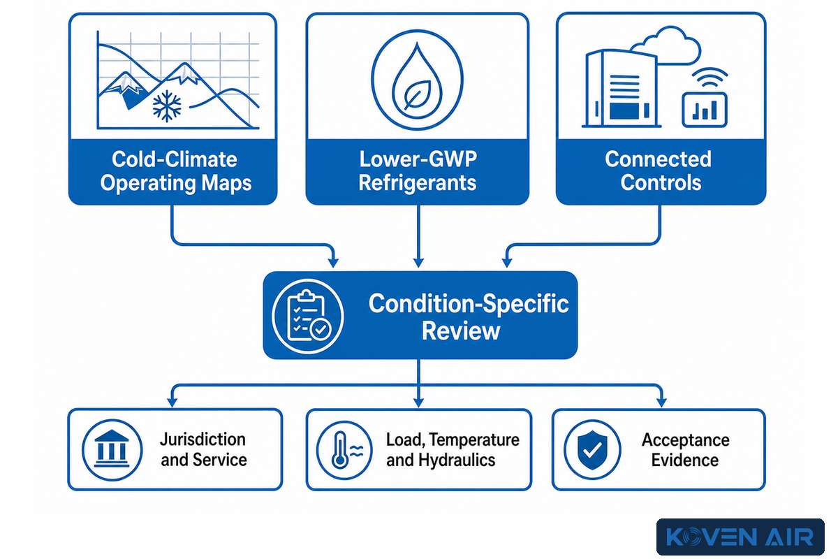
Progress on a project question is most constructive when it shows how wider cold-climate operating maps, lower-GWP refrigerants, or connected controls change the condition of concern. Condition-specific reviews remain necessary for controls, jurisdiction, service, operating data, load, temperature, hydraulics, and acceptance evidence. The risk is that those condition-specific reviews can still miss jurisdiction, service, operating data, load, temperature, hydraulics, or acceptance evidence when a date-bound United States rule is treated as universal.
US refrigerant rules illustrate the importance of dates, time, and scope. The EPA May 2026 fact sheet says the final rule removed the January 1, 2026 installation deadline for qualifying residential and light-commercial heat-pump equipment made in or imported into the United States before January 1, 2025. This qualifying equipment may now be installed while supplies last. The EPA’s statement is specific to the US and does not establish an international or global refrigerant rule.
Project teams should identify equipment sector, jurisdiction, manufacture or import date, installation date, safety classification, local code, service plan, and the current rule. Incentives and tax treatment also change by place and time; verify them during procurement instead of embedding a temporary assumption in the technical design basis.
Turn the Guide into a Project Brief
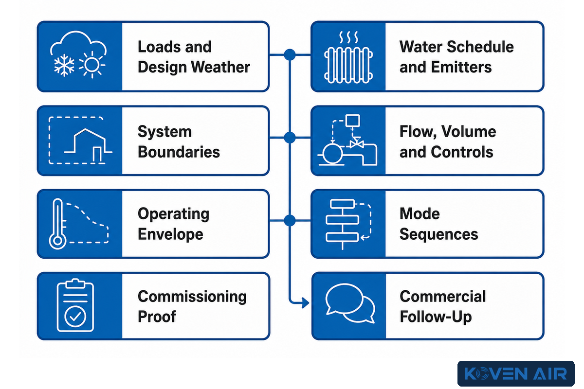
A good project brief is a compact evidence package. It allows engineers and suppliers to assess the same duty without requiring them to turn initial conversations into competing catalog claims. The brief should separate verified inputs, calculated assumptions, open questions, commercial follow-up, and acceptance tests. This is especially important to outline the reasons for each change made to the brief.
- Freeze room and zone loads, design weather, schedules, and load-duration factors.
- Propose a water-temperature schedule and correct all critical emitters to it.
- Draw the hydronic and refrigerant boundaries, including outdoor water exposure and failure states.
- List maximum and minimum flow, active volume, zone states, pump duties, and control sensors.
- Compare maximum capacity, minimum output, defrost, backup, and electrical demand at named conditions.
- Write mode sequences for heating, cooling, DHW, alarms, outages, and recovery.
- Define the Four-Point Commissioning Proof Set, sensor accuracy, test conditions, and deferred tests.
- Keep models, configurations, pricing, quotations, and RFQs on the commercial page.
According to Koven Air’s company information, the business was launched in 2007, operates a 20,000 m² facility in Suzhou, has operations in over 35 countries, and tests equipment prior to shipping. This information provides company context; applying codes, water-safety requirements, and acceptance criteria still requires qualified site review.
Related system information is available in Koven Air’s heat pump range, water-source systems, and cold-climate heat pump solutions. Use these for commercial configuration follow-up after the hydronic brief is complete.
Bring a defined duty, not only a capacity request
Share the load, water schedule, emitter check, piping boundary, flow states, operating envelope, mode sequence, and acceptance plan with the solution team.
Share the load, water schedule, emitter check, piping boundary, flow states, operating envelope, mode sequence, and acceptance plan with the solution team.
Frequently Asked Questions
Common questions often sound simple because they omit the operating condition. The answers below give the decision boundary first and point back to the evidence a project team should collect. Manufacturer instructions, local code, and qualified design remain controlling for the installed system.
Can an air-to-water heat pump use existing radiators?
Check output at the proposed water temperature
Yes, in some buildings. Calculate the room load and correct each radiator’s output to the proposed mean water and room temperatures. Oversized radiators may have useful spare area, while other rooms may need more emitter area, fan assistance, envelope work, or a different schedule. Radiator age alone doesn’t answer the question.
Does every air-to-water heat pump need a buffer tank?
No; define the function first
A buffer may supply active water volume, longer run time, hydraulic separation, defrost support, or load shifting. Some systems already satisfy flow and volume limits through distribution and control design. State the smallest load, minimum output, required flow, active volume, zone states, and target run time before sizing or omitting a tank.
Is monobloc safer than split in freezing weather?
Safety depends on the exposed circuit and protection plan
Monobloc commonly places water outside, so freeze exposure, outages, fluid properties, piping route, drains, alarms, and backup measures require review. Split equipment commonly moves the water-side interface indoors but adds field refrigerant work. Draw the actual boundary and assess failure modes, local weather, access, code, service capability, power-loss response, and manufacturer requirements. Neither label eliminates the need for a documented fault test and maintenance owner.
Can one system provide heating, cooling, and domestic hot water?
Capability and simultaneous duty are different questions
Some arrangements can serve all three, but the sequence must manage different temperature requests, priorities, storage, valves, pumps, dew-point protection, latent load, hygiene requirements, and recovery time. Define whether duties are simultaneous or prioritized and test each transition. A list of supported modes doesn’t prove that every mode can be served at once. For example, a domestic-hot-water priority call may pause space heating, while radiant cooling may require a separate air system to carry ventilation and moisture loads. Record the permitted overlap, maximum priority time, recovery sequence, failure state, and the sensor that ends each mode.
What data should be recorded during commissioning?
Record the condition together with the result
At minimum for the project framework in this guide, record water flow, entering and leaving water temperatures, electrical input, and the stable control response. Add outdoor and indoor conditions, setpoints, zone and valve states, pump speed, backup status, units, sensor locations, calibration information, and synchronized timestamps. Compare the measured point with approved design and manufacturer data.
References & Sources
This guide builds design and system logic from currently available public, institutional, standards-body, and named trade sources. Conditions and jurisdiction are retained in the text so a reader can distinguish general design logic from a case, a water-loop measurement analogy, or a United States rule.
- MassCEC: Air-to-Water Heat Pumps
- US DOE: Guide to Sizing and Selecting Air-Source heat pumps
- PNNL: Heat Pump Quality Installation and Commissioning
- PNNL: Ground-Source Heat Pump O&M Best Practices
- US Federal Register: Split and Monobloc Configuration Record
- ASHRAE: Energy Efficiency Measures to Consider
- US CDC: Monitoring Building Water
- AHRI: Standards Overview
- US EPA: May 2026 Technology Transitions Final Rule Fact Sheet
- Plumbing & Mechanical: Hydro-Split Air-to-Water Case
Final takeaway
A sound air-to-water project connects the real load, the lowest workable water temperature, emitter output, hydraulics, operating envelope, mode logic, and measured acceptance evidence. Equipment selection follows that record.
A sound air-to-water project connects the real load, the lowest workable water temperature, emitter output, hydraulics, operating envelope, mode logic, and measured acceptance evidence. Equipment selection follows that record.
Factory Selection Support
Turn this guide into a usable HVAC RFQ package.
Share design conditions, airflow, temperature, humidity, process load, room use, and scope boundary. Koven Air can recommend a practical equipment route before quotation.
7equipment families
ISO / GMPcleanroom review
RFQscope comparison
What to prepare before quote
- Use settingCommercial building, cleanroom, hospital, data center, process area, or retrofit.
- Operating conditionsAirflow, load, temperature, humidity, static pressure, and duty hours.
- ConstraintsFootprint, access, hygiene class, material, controls, documentation, and delivery boundary.
Final equipment selection depends on local codes, project drawings, and confirmed site conditions.