
Get in Touch with Koven Air Company



Fan coil units are the workhorse terminal device of commercial chilled-water HVAC, a fan, a water coil, and a filter that turn a central plant’s hot or cold water into comfortable air, zone by zone, without threading ductwork through every room. As a fan coil unit HVAC category, commercial fan coil units and their close relative the hydronic fan coil unit cover the full spread of types of fan coil units in use today. This guide breaks down how they actually work, where each body style fit, how they compare against VAV boxes and full air handling units, and what separates a dependable manufacturer from a reseller.
A fan coil unit conditions room air by drawing it through a filter and across a hot or chilled water coil, then returning it to the space with a built-in fan. Each unit covers roughly 340–2,380 m³/h of airflow and serves one zone independently, from a hotel room to a full office floor, without central ductwork.
Key Points
- Fan coil unit return-air filtration typically runs behind a central air handling unit’s deeper filter bank, a real indoor-air-quality trade-off, not just a comfort one.
- The existing standard for fan-coil energy rating, AHRI 440-2019, and AHRI-440 hydronic coil have a special exemption according to ASHRAE 90.1.
- In four-pipe systems, hot and cold circuits serve various zones heat, while in two-pipe systems the entire building is served by the same circuit according season.
- Most projects consider central air handler rooms to be rentable space not “lost” space- that reframes the argument fan coils is making.
- Hydronic means a connection to water and not the unit type. From light-commercial installs to residential hydronic fan coil units in a condo retrofit, the body style (horizontal, vertical, recessed, cassette, exposed) is independent of that water connection.
Quick Specs
| Model range | KAFP-02WA to KAFP-14WA (Koven Air reference range) |
| Air volume | 340–2,380 m³/h |
| Cooling capacity | about 2.25–13.53 kW |
| Heating capacity | about 3.40–20.19 kW |
| External static pressure | 12 / 30 / 50 Pa options |
| Sound pressure | 42–56 dB(A) at 50 Pa |
| Water & power | DN20 inlet/outlet/drain; 110V or 220V |
How Fan Coil Units Actually Work
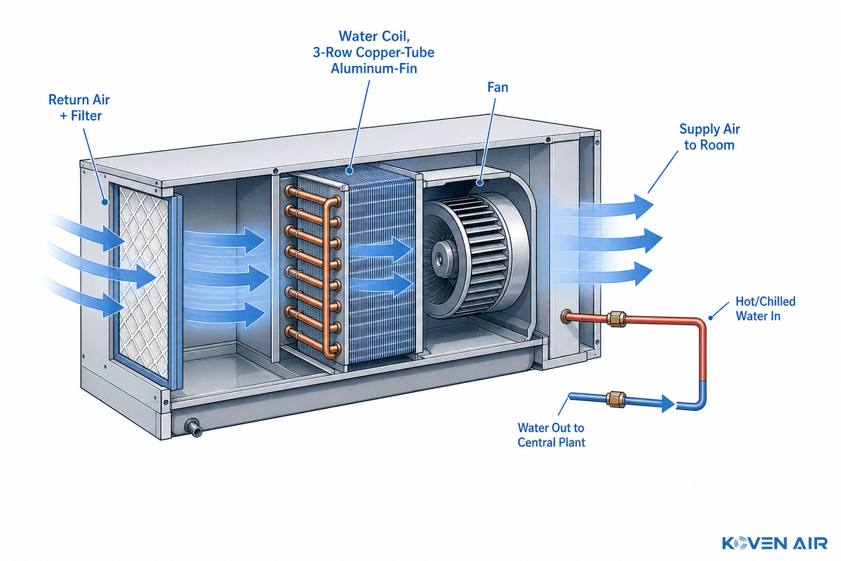
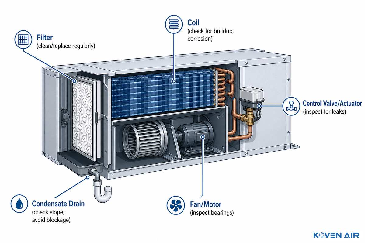
A fan coil unit (FCU), also known as a blower coil unit, is a compact terminal piece of equipment comprising a fan, an aluminum-fin copper tube water coil (a mini heat exchanger), and a filter in a single sheet-metal chassis. From a central plant (boiler, chiller, heat pump) supplied by the building’s chilled-water or hot-water supply, a flow of hot or cooled water travels through insulated pipes up to the device.
The water coil is generally of the copper-tube, aluminum-fin construction, usually a 3-row coil with typical working pressures up to 1.6 MPa or so on the water side. It helps to visualize a very basic fan coil unit diagram: room air in to the filter, across the water coil, condition air out. The fan pulls the air in through the filter and across the coil, where it adds or removes heat by direct contact, then the conditioned air is piped back out to the room. No refrigerant is in the fan coil unit itself, and, in most cases, no additional ductwork runs beyond a short supply-and-return loop to that FCU.
That’s the major distinction between these units and refrigerant-based split systems, which handle heat via compressor and refrigerant line set, not a water loop; that’s why fan coil units can scale into dozens of zones from a single plant rather than requiring an outdoor compressor for each.
How Does a Fan Coil Unit Work in an HVAC System?
Within a hvac system, the fan coil hangs off the end of a hydronic loop, which originates from a chiller or boiler (or sometimes just a heat pump). Individual branch loops carry hot (or cooled) water to each unit, opening/closing a valve to feed the coil based on the fan coil’s thermostat. The fan is controlled in an on/off manner or it cycles, and each zone responds to its own independent call.
Two families of these units are typically seen: those where the fan come after the heating or cooling coil (a blow-through arrangement) pushing the air across it, and where the fan is before the coil pulling air through it (a draw-through design). Draw-through designs offer better thermal performance by utilising more of the heat transfer surface, but are more expensive because of an integral fan mounting structure and air column, something most manufacturers are reticent to feature in spec sheets. Stuck valves and miscalibrated thermostats are common enough failure points that the National Institute of Standards and Technology has published a dedicated tool for evaluating fault-detection and diagnostic methods specific to fan coil units.
💡 Pro Tip
Ask shortlisted manufacturers if their fan coil is blow-through or draw-through prior to considering the relative sound and capacity levels between them. These two designs are not thermally equivalent even at matching airflow.
Control has evolved from on/off fans to DC and EC (electronically commutated) fans, which accept a 0-10V signal; the fan runs at 0-10V and stops completely below approximately 2.5V and comes up to full speed at 10V. In most commercial fan coils, manufacturers tune controls to stay in the 4–7.5V range, fans under 4V deliver less-than-useful airflow, and above 7.5V fans get too noisy for occupied offices, so different brands of otherwise-similar fan coils can end up louder or quieter relative to each other while producing similar amounts of air.
The Fan Coil Body Styles at a Glance: Horizontal, Vertical, Concealed, Cassette
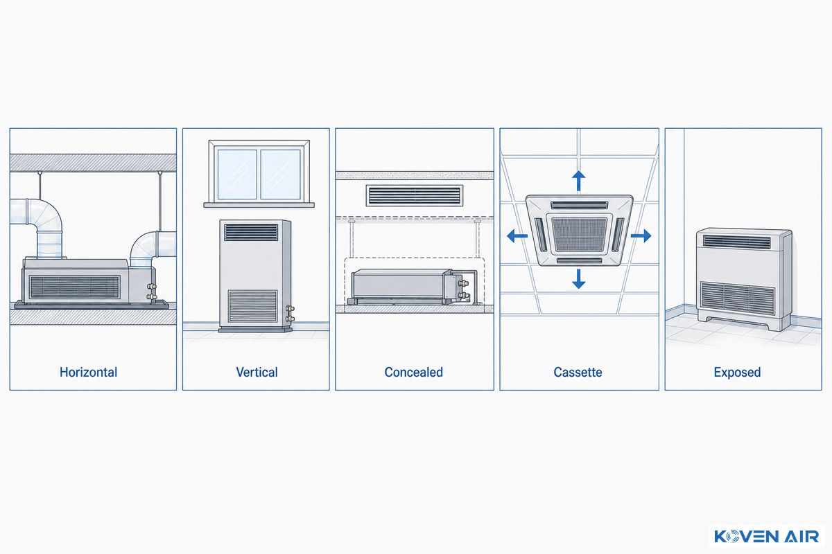
“Hydronic” describes the water-based piping system connected to a fan coil, not the unit’s form factor. If you’ve got the chilled water loop plumbing, you’ve hydronic fan coils regardless of Whether you’re installing them at floor or at head end of your run, in ceilings, at ceiling height, or at wall height or as a part of a multi rise building: this just refers to where physically you’re installing your fan coil, how is your air spread out (whether from ceiling, from floor, at one corner of the room or throughout the entire ceiling and many more scenarios). Hotels, industrial plants with both office and shop floor zones etc – all these are valid applications of the fan coils.
| Body style | Typical install zone | Best fit |
|---|---|---|
| Horizontal | Ceiling void, ducted | Offices, corridors, hotel floors |
| Vertical | Floor, under-window | Perimeter rooms, retrofits, high-rise glazing zones |
| Concealed | Ceiling or wall cavity | Hotel rooms, quiet zones needing an invisible finish |
| Cassette | Grid ceiling, 2- or 4-way discharge | Open-plan lobbies, libraries, retail floors |
| Exposed | Wall or floor, finished cabinet | Spaces without ceiling access or budget for concealment |
Choosing the wrong body style is a costly mistake to discover late, because a concealed unit specified for a space that turns out to have no ceiling void means cutting into finished surfaces or re-ordering an exposed model, a delay that can run into weeks on a live project. Koven Air’s pre-sales team flags this risk during parameter verification precisely because it happens often enough to be worth a dedicated check. Especially for high-rise applications, vertical units are commonly stacked from floor to floor and tied into a shared piping riser, a single supply-and-return run threaded through the building structure can serve every floor on that stack, which is why placement gets decided early, while the shaft space is still being planned. Lower-rise industrial buildings favor a different trade-off: exposed, freestanding, or wall-mounted cabinet units at floor or wall level, where a service technician can reach the coil and filter without ceiling access at all. For a deeper look at ceiling-mounted installation constraints specifically, see our concealed fan coil unit installation guide, and Koven Air’s own vertical fan coil unit and horizontal fan coil unit product pages for model-level specifications.
Fan Coil Units (FCU) vs Other HVAC Terminal Devices: VAV, PTAC, Heat Pumps, and AHUs
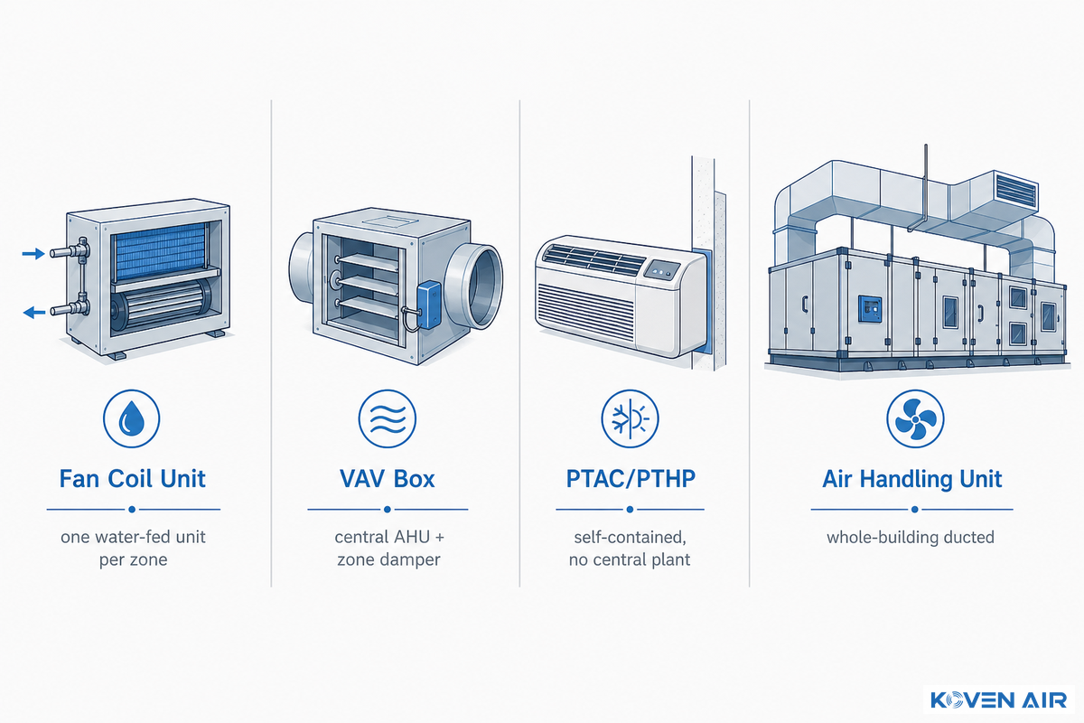
But before deciding between fan coil units, first question is: ARE FCUs the correct equipment category?
Instead of the alternatives, VAV boxes supported by a central air handling unit, packaged terminal units (PTAC/PTHP), or standalone heat pumps, FCUs make different choices on how to support zoning, and the compromises aren’t as simply phrased as “FCU saves space.”
4-Way Terminal Unit Crosswalk
Quick reference comparing the typical application of FCU, VAV, PTAC / PTHP, and AHU design approaches.
| Terminal / system type | Zoning method | Ductwork need | Typical building type |
|---|---|---|---|
| Fan coil unit | One water-fed unit per zone | Minimal — short supply/return runs only | Hotels, hospitals, mixed-load offices |
| VAV box | Damper modulates airflow from a central AHU | Full duct network per zone | Large offices, buildings over roughly 25,000 sq ft per ASHRAE 90.1 baseline rules |
| PTAC / PTHP | Self-contained through-wall unit, no central plant | None | Hotel guest rooms, single-tenant retail |
| Air handling unit (AHU) | Central unit distributes to many zones via ductwork | Full building duct network | Data centers, cleanrooms, large single-load floors |
| Unit ventilator | One unit per zone, like an FCU | Minimal, but rated for up to 100% outdoor air intake | Classrooms and spaces with high fresh-air ventilation demand |
| Chilled beam (active/passive) | Radiant + induction cooling per zone | Primary air duct only (active type) | Offices prioritizing low fan noise and no condensate pan |
| Ductless split system | Refrigerant-based, one outdoor unit per indoor head or small group | None | Small retrofits without a hydronic loop available |
| Dedicated outdoor air system (DOAS) | Building-wide fresh-air delivery, paired with FCUs for sensible load | Central ventilation duct network | Any FCU building needing code-compliant outdoor air |
| Packaged rooftop unit (RTU) | Self-contained, often single-zone or short duct runs | Roof-to-space duct run | Big-box retail, single-story commercial |
What Is the Difference Between a Fan Coil Unit and an Air Handling Unit?
At the heart of it, fan coil units are compact, room-level terminals that deliver heating and cooling to a single zone through their fan and coil. An air handling unit (AHU), on the other hand, serves multiple rooms or an entire floor, providing filtered conditioned air to a large section of a building.
While AHUs concentrate the filtration and outdoor air treatment, FCUs provide individualized temperature and fan control with low maintenance requirements and a smaller space footprint. Koven Air builds both categories, see our air handling units line for whole-building ducted applications.
Filtration is one area where these systems differ in ways not immediately evident on sales brochures: FCU filters, being smaller, are limited in size, depth and, often, efficiency compared to the sophisticated filtration found within an AHU. this is a notable indoor-environment quality concern in high occupancy, high traffic or infection control type buildings, making it less of an opinion than an engineering fact – it adds another factor that’s best discussed with an engineer.
An old debate on a widely followed engineering forum highlighted the trade-off very effectively.
After a ten-floor building considered switching from central AHU-plus-VAV to floor-by-floor fan coil units, one participant pushed back on the “FCUs save space” assumption directly: “mechanical rooms are rentable space prorated per tenant similar to toilets and corridors,” and architects routinely grant 600 to 1,000 square feet for an AHU room without pushback. Other participants weighed in with the flip side, more FCUs mean more control valves and more filters to maintain per floor, and noted that ASHRAE 90.1’s baseline system rules often push larger, multi-story buildings toward VAV-based systems in the first place.
So the realistic truth in this debate was, FCUs clearly win on low maintenance individual room control and AHUs clearly win on centralized filtration, with overall building size being the determining factor.
For a fan coil, the official performance rating standard is now AHRI 440-2019 (R2024). Under ASHRAE Standard 90.1, hydronic fan coils rated to AHRI 440 are granted a specific exemption from certain coil-sizing requirements.
But another, essential boundary belongs in this comparison: a standard fan coil unit is a recirculation device, not a ventilation-air source. ASHRAE’s own systems-and-equipment guidance draws exactly this line, treating fan coil units as suited to spaces where outdoor-air demand is minimal or handled elsewhere, and contrasting them with the adjacent “unit ventilator” category, a terminal built to supply up to 100 percent outdoor air on its own.
The importance of this differentiation for health care, at least, becomes regulatory; Centers for Disease Control & Prevention infection-control guidelines specifically direct that the use of “through the wall units and fan coil units be limited to recirculating use with all outside air requirements furnished by another supply air system… supplying outdoor air at a rate not less than 2 outdoor air changes” for general patient rooms, and any room served solely by individual through the wall units can’t be classified as either an Airborne Infection Isolation or a Protective Environment room. For virtually any application involving fresh-air ventilation-be it a health care setting, a school, or a densely-populated commercial office building-the implication is that such units will be required to accompany a central air handler or special outdoor-air unit that supplies adequate ventilation air; they aren’t designed to perform that function alone.
2-Pipe vs 4-Pipe: The Engineering Reasoning Behind Water-Loop Design
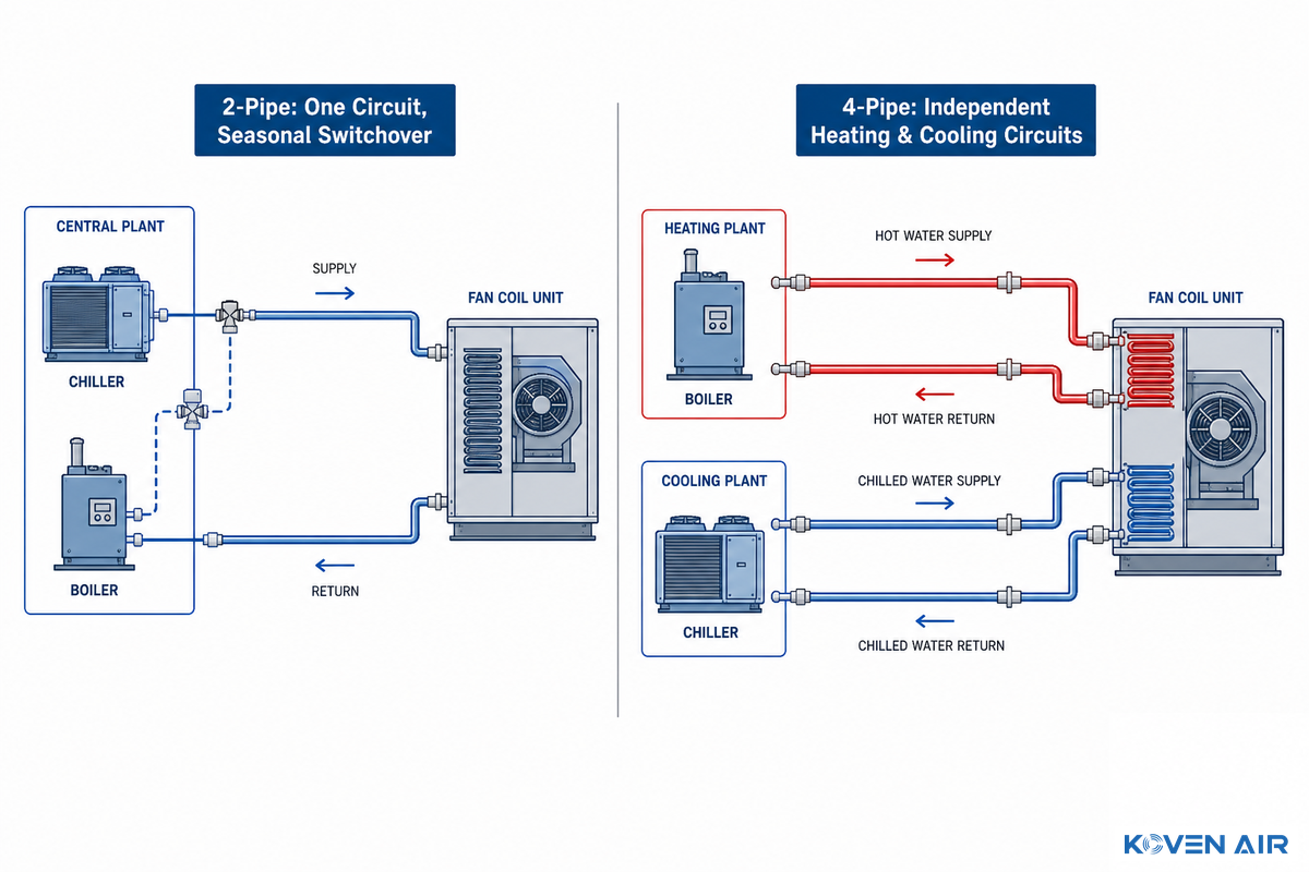
A two-pipe chilled water system uses a single supply-and-return water loop to each unit, which either delivers hot or chilled water at a time, allowing a system to either go into heating mode or cooling mode simultaneously as a whole system, and typically this switches by season. Four-pipe systems, by contrast, run a hot-water loop and a chilled-water loop to each fan coil, so each zone’s control valve can call for heating or cooling independently.
Specifying the wrong pipe configuration is an expensive mistake to walk back, because retrofitting a two-pipe building to four-pipe after construction means running an entire second water loop through finished ceilings — a rework Koven Air’s engineering team sees requested often enough that pipe configuration is the first question on any project intake form, not an afterthought.
What Is the Difference Between a 2-Pipe and a 4-Pipe Fan Coil System?
The difference is about simultaneity – not pipe count. A 2-pipe system cant give one room heating while a neighboring room wants cooling – thermostat setpoint changes are functional, but underlying water temp comes from what ever the central plant send to the whole system that day.
A 4-pipe system over comes this, a north facing conference room that wants heat can get it, while a south facing private office wants cooling, both from the same central plant in unison because each FCU’s heating and cooling coils will source from disparate circuits, both centrally controlled by its own valve.
That extra pipework is why four-pipe systems have a higher installation cost – additional pipe, valves, and pumping, but it’s also why these systems so commonly “win the lot” in the type of building that has true simultaneous mixed loads: hotel with shaded and sunlit rooms on one level; a hospital where the patient can’t wait until summer for a coil to switch from heating to cooling; a lab or mixed use building with all kinds of widely different internal heat gain from room to room.
“A four-pipe fan coil unit system is cost-effective from a chilled-water and heating-water pumping perspective. Because the unit transfers heat to the space using forced convection, the coil heat-transfer area required is reduced compared to a chilled beam, which relies on natural convection, and the reduction in coil surface area results in lower water-side pressure drop and lower pumping energy.”
Ljungquist’s own case study is a useful data point rather than a universal promise: a four-pipe fan coil system built for a large higher-education housing facility, paired with a dedicated outdoor-air unit with heat recovery, demand-controlled ventilation, a high-efficiency chilled-water plant, and ECM fan motors, modeled at roughly 42 percent energy-cost savings against the ASHRAE 90.1-2010 baseline building for that specific project. That’s one documented case, not a guaranteed number for every building, but it shows how much of the four-pipe system’s efficiency comes from the supporting plant design, not the fan coils alone.
On the project-level question of what the pipe arrangement is for a particular building, Koven Air’s fan coil units decision matrix walks the user through season mode, room diversity, and humidity control signal by signal – this section is about why the two systems work differently, not about which system to select for a building.
How Engineers Actually Size a Fan Coil Unit

Figuring out the right size of a fan coil unit requires a series of interlocking choices, not one. Cooling load and heating load define the initial capacity target; airflow and ESP explain how much of that capacity realistically reaches the room; and noise constraints show where airflow gets capped even before the fan become the loudest sound in the room.
3-Question FCU Category Filter
Before someone cracks open a spec sheet, three questions can drastically pare down your fan coil options: where do they access room? how much duct can be run? how sensitive is space to sound?
If → Then
- If you can run ceiling and your duct runs can remain short the horizontal body style (usually hidden bodies) are the most inexpensive solution.
- With fixed floor area and no vertical void, ceiling on Floor Mounted solutions provide an ideal solution for perimeter rooms which serve as perimeter zones.
- If it’s considered sound-sensitive area (e.g. bedroom, quiet office, examination room) aim for the lowest end of the range and the sound level is checked at the operating static pressure of the units and not max static pressure of design.
📐 Engineering Note
An often quoted airflow metric for residential equipment in the Bonneville Power Administration’s PTCS program is to Size Ducted Equipment at approx 325-500CFM/ton – useful for sanity checking order-of-magnitude issues with ducted systems but not to be relied on as the basis for selection with a Commercial AHRI 440 rated Fan Coil, for which the Manufacturer’s own ratings should always be consulted. UK industry standards (HEVAC/FETA) have a common external static pressure set-point for ducted fan coil testing of 50Pa duct resistance, which also falls within Koven Air’s top 12/30/50Pa ESP range – a perfectly reasonable assumption for a reasonably constrained commercial duct-run with grilles. On the design air side, typical ranges for the design of ducted commercial fan coils would be something like 700-900FPM at the supply fan, 500-700 FPM at the branch ducts, and 300-600 FPM at the grille face; Supply & Return grilles usually need to be at least 3.5′ and no more than 5′ apart to avoid shorting out. Likewise to airflow, the physical installation requirements dictate whether a hidden installation is appropriate, typical hung concealed units usually drop from four M10 (3/8”) rods, need about 300mm of void clearance behind, and a 450mm × 450mm (18″ × 18″) panel, for the drain lines – make sure they slope no less than 1%.
Thermostat and control-valve-actuator selection comes after sizing, not before. A correctly sized unit controlled with a simple on/off thermostat will short-cycle in shoulder-season conditions, while the same unit on a modulating valve and BMS-tied control can deliver far smoother temperature control across a wider load range. Tying that control loop into a building management system adds occupant-based scheduling, an empty conference room doesn’t need full airflow at 7 a.m. — without changing anything about how the fan coil itself is sized. The other question worth asking early, and rarely asked early enough, is how many fan coil units the central plant itself can actually support: a chiller, boiler, or heat pump sized for today’s zone count leaves no headroom for a future floor buildout, so total connected load, not just individual unit capacity, belongs in the same sizing conversation. For a deeper look at which body style fits which install constraint, see the body styles comparison above, and for the water-loop side of the decision see 2-pipe vs 4-pipe reasoning.
What to Check When Evaluating a Fan Coil Unit Manufacturer

Reliability is linked directly to the factory that built the unit and spec-sheets don’t go into production quality. Be careful on making a decision based purely on specs and you need to ask for production evidence, not just marketing language.
Factory-to-Field Traceability Score
Check-sheet to qualify production control by fan coil unit manufacturer – from raw materials to test before shipping.
Ask for evidence of:
- Standardize process control – the supplier must provide evidence of a documented, consistent procedure for manufacturing instead of a generic commitment.
- Precision machining and sheet-metal process controls, with inspection points named.
- Manufacturing-process trace points – can a specific unit’s build history be pulled by serial number?
- A pre-shipment aging or burn-in test, with a stated duration
- A named after-sales process – who answers a warranty call, and what’s the response commitment?
As a manufacturer, Koven Air documents this end to end: 18 standardized production processes, 23 sheet-metal precision-machining processes, 400 manufacturing-process trace points, 36 factory inspections, and a 24-hour aging test before any unit ships, backed by a three-stage service model – pre-sales load and parameter verification, in-sales on-site installation and debugging support, and after-sales lifetime free technical guidance with immediate issue resolution during the warranty period. Advanced hvac buyers sourcing for hospitals, offices, and other commercial applications should expect customizable configurations – voltage, controls package, and pipe layout – to be a normal request, not a special-order exception, and should expect similarly specific numbers rather than marketing language from any unfamiliar manufacturer before committing to a large order.
Procurement teams sourcing internationally add one more filter: not every “strict QC” claim survives contact with a real inspection. One useful gut-check is asking a candidate manufacturer whether a third-party pre-shipment inspection is welcome, and whether serial-number-level production records are available on request – a factory with real traceability has no reason to hesitate on either question.
What Actually Drives Fan Coil Unit Cost

There’s no honest single “fan coil unit price” – published unit prices vary by an order of magnitude depending on capacity, coil configuration, and controls, and public list pricing for commercial hydronic fan coils isn’t consistently available the way it’s for packaged residential equipment.
What can be laid out clearly is which inputs actually move the number:
- Capacity and coil configuration – 2-pipe units cost less than 4-pipe units of equivalent capacity because of the extra circuit, valves, and coil rows.
- External static pressure rating – higher-ESP units need a stronger motor and fan assembly, which adds cost and, usually, noise.
- Controls package – a simple on/off thermostat costs far less than a modulating valve with a BMS-integrated digital controller.
- Voltage and regional compliance – 110V vs 220V, and destination-market certification requirements, affect both the unit and the supporting electrical work.
- Quantity, packing, and freight – for multi-unit projects, freight and packaging can move the landed cost as much as the unit price itself.
Because the AHRI 440 rating standard sets the test conditions manufacturers use to publish capacity numbers, comparing two quotes at the same AHRI-rated airflow and water temperature is the fastest way to tell whether a lower number reflects a genuinely smaller unit or an apples-to-oranges test condition. A procurement team that sends a full room schedule – cooling and heating load, airflow, ESP target, pipe configuration, voltage, and quantity – gets a quote path instead of a guess; sending “what’s your price for a fan coil unit” gets a range wide enough to be useless.
The risk in skipping that step is real, because a buyer comparing two quotes at different AHRI test conditions can end up rejecting the better-built unit as “too expensive” when the actual mistake was comparing 340 m³/h against 380 m³/h and calling it apples to apples. Koven Air’s pre-sales calculation review exists specifically to catch this kind of mismatch before it becomes a contract dispute.
Fan Coil Unit Limitations and Maintenance Basics
✔ Advantages
- Independent room-level control with minimal ductwork
- Less fan energy per zone than an all-air VAV system
- Compact enough for tight ceiling voids and retrofit projects
- Fast to replace unit-by-unit without disrupting the whole floor
⚠ Limitations
- Filtration efficiency typically trails a central AHU’s filter bank
- More total control valves and filters to maintain than one central AHU
- Units over roughly 2,000 CFM commonly need smoke-detector and fire-alarm interlocks
- ceiling-mounted units risk condensate leaks into occupied space if drainage is neglected
Common failure modes are consistent across the industry: clogged or neglected return-air filters that quietly throttle airflow long before anyone notices reduced comfort; condensate-drain blockages caused by condensation buildup that shows up as ceiling stains rather than an obvious mechanical alarm; degraded pipe insulation that lets a chilled-water line sweat onto a finished ceiling – and in concealed ceiling-void installations, that insulation also has to meet NFPA 90A’s fire-performance limits (a flame spread index of 25 or less and a smoke developed index of 50 or less, tested to ASTM E84), which is worth confirming on the submittal rather than assuming after the fact; and control-valve or actuator faults that leave a zone stuck in heating or cooling regardless of thermostat setpoint. A US patent for an adjustable condensate drain pan with integral overflow protection exists specifically because standard drain pans in fan coil applications have a documented history of overflow incidents when the primary line clogs – a sign of how common the failure mode is industry-wide.
Baseline regular maintenance checklist
- Clean or replace return-air filters on a fixed interval, not just when airflow visibly drops
- Inspect the condensate pan, trap, and drain line at the start of the cooling season
- Check control valve and actuator operation, not just thermostat wiring
- Confirm access-panel clearance is still real after any interior renovation work
Concealed units above finished ceilings carry an extra service-access risk worth planning for at design time, not discovery time: a drain line without enough fall, or an access panel that ends up blocked by a later tenant fit-out, turns a routine filter change into a ceiling-demolition job. Our concealed fan coil unit guide covers duct sizing and access-panel planning for exactly this scenario in more depth.
Industry Outlook: What’s Changing in Fan Coil Selection

The retrofits driven by energy efficiency mandates – not sheer market-share growth – are the ones to track. US Infrastructure Investment and Jobs Act funding along with the DOE’s Better Buildings Initiative is directing capital toward HVAC retrofits that favor zoned-level control and minimal lifecycle operating cost, an advantage four-pipe fan coil architecture holds over two-pipe and all-air systems in larger, mid-rise structures. Even the DOE’s zero-energy building HVAC guidance makes this case: its example schema advocates combining a cooled/heated water fan coil unit with a dedicated outdoor air system as an ideal configuration to simultaneously maximize energy efficiency, comfort, and indoor air quality, thereby positioning the fan coil unit’s role, within broader building heating and cooling systems, as zone-level delivery and nothing more.
In Europe, the Energy Efficiency Directive – mandating 3% annual energy-efficiency improvements for public buildings – is directly decreasing lead times for asset replacement. For a spec written today: If the building use case reasonably supports heating and cooling to more than one zone simultaneously, it would be wise to price for an energy-efficient four-pipe unit now rather than spec a two-pipe system and face a capital HVAC retrofit project on the legacy equipment five years from now.
On the product end, there are two definite developments (rather than generic “smart-building” talk) based on patent filing: systems that can be physically adjusted to manage their condensate overflow (to limit failure events), and, in air-quality-focused situations like hospitals or schools, photocatalytic air-purifying technologies inserted into the coil section itself. While neither solution would meet every need today, both reflect manufacturers actively addressing the two weakest areas the guide already cited, rather than simply pursuing gains in efficiency.
Koven Air tracks both directions because the risk of ignoring them is a spec that reads current today and dated within a year or two, as buyers in regulated industries increasingly ask for condensate-overflow protection and IAQ features by name rather than accepting a bare-bones unit and retrofitting later.
(Market-size estimates for the global fan coil unit category, commonly cited in the low single-digit billions of dollars with mid-single-digit percentage annual growth, are directional context from third-party market research firms, not independently audited figures, and aren’t the basis for the guidance above.)
FAQ: Fan Coil Units
Q: What is a fan coil unit for?
View Answer
A fan coil unit heats or cools a single room or zone by pulling air through a filter and passing it across a hot or chilled water coil, then sending the conditioned air back into the space — without needing central ductwork or a dedicated outdoor condenser for that room. It’s the room-side terminal of a larger hydronic system that also includes a central boiler, chiller, or heat pump supplying the water.
Q: What are the disadvantages of a fan coil unit?
View Answer
Watch for filtration that trails a central air handler’s, more individual components that need service (filters, fans, valves), condensation drips if you ignore the drain, and a need for fire-code interlocks above around 2,000 CFM. A bigger model number doesn’t fix any of that — but smart planning for access, drains, and controls at the design stage can.
Q: Do fan coil units use a lot of electricity?
View Answer
The fan coil unit itself mainly powers its fan and controls – most of the system’s total energy use happens at the central chiller, boiler, or heat pump producing the hot and chilled water. Tuning a well-controlled EC fan motor to the effective 4-7.5V range, rather than running it wide open, keeps that fan-side draw modest.
Q: How much does a new fan coil unit cost?
View Answer
Cost depends on capacity, 2-pipe vs 4-pipe configuration, ESP rating, controls, voltage, and order quantity – there is no reliable single figure. Send a room schedule and water conditions for a usable quote path.
Q: Is a fan coil unit the same as air conditioning?
View Answer
Not quite. “Air conditioning” is a broad term for any cooling system, including standalone refrigerant-based units. A fan coil unit is specifically the room-side hydronic terminal – it needs a separate chiller, boiler, or heat pump to supply its water, whereas a self-contained AC unit carries its own refrigeration circuit.
Q: Do fan coil units require ductwork?
View Answer
No – each unit conditions its own room directly without ductwork. Concealed and cassette styles may use short duct runs to reach a grille, but there is no building-wide duct network the way a central air handling unit requires.
Q: What maintenance does a fan coil unit require?
View Answer
Plan on regular filter cleaning or replacement on a fixed schedule rather than waiting for a visible comfort complaint, an annual condensate pan and drain-line inspection before the cooling season starts, and periodic control-valve and actuator checks so a stuck valve doesn’t leave a room heating when it should be cooling. Confirm access-panel clearance hasn’t quietly been blocked by a later renovation, fit-out, or storage rack – this is the single most common reason a routine filter change turns into a half-day job. Concealed and ceiling-mounted units deserve extra attention to drain slope specifically: a line without enough fall can carry water slowly enough that nobody notices until a ceiling tile below stains or sags, by which point the insulation around the pipe run has usually already absorbed moisture and needs replacing along with the tile.
Q: Can Koven Air customize fan coil units for a project?
View Answer
Yes. Send the room schedule, water conditions, voltage, quantity, and any site access limits, and Koven Air’s pre-sales team will run the parameter verification and calculation review before quoting – the same process used for the 35-country installed base referenced throughout this guide.
Ready to spec a fan coil unit for your project?
Send your room schedule, water conditions, and access constraints – Koven Air’s full fan coil units line covers horizontal, vertical, concealed, cassette, and hydronic configurations with factory testing and lifetime technical support. Koven Air’s pre-sales team checks your load and airflow numbers against the AHRI-rated capacity before a quote goes out, so the unit that ships is sized for the room, not just for the spec sheet.
Why We Write This
Most fan coil content online is either a bare product catalog or a one-paragraph glossary definition – even the Wikipedia entry on fan coil units carries the platform’s own “relies on a single source” quality flag. We wrote the VAV/PTAC/AHU comparison and the manufacturer-evaluation section because a 35-country installed base shows buyers often confuse the equipment-category decision with the model-selection decision. Reviewed by the Koven Air Environment Technology Co.,Ltd technical team.
References & Sources
- AHRI 440-2019 (R2024): Performance Rating of Fan-coil UnitsAir-Conditioning, Heating, and Refrigeration Institute
- ANSI/ASHRAE/IES Standard 90.1-2022 Addendum (fan-coil coil exemption, Section 6.4.7)ASHRAE
- PTCS External Static Pressure, CFM Manufacturer Lookup TablesBonneville Power Administration
- A Tool for Evaluating Fault Detection and Diagnostic Methods for Fan Coil UnitsNational Institute of Standards and Technology
- Field assessment of economy fan coil unit performance in cooling capacity and acoustic compliancePMC / National Library of Medicine, 2025
- Fan coil unitWikipedia
- Four-pipe Fan Coil Unit Systems: Is It Right for Your Facility?FacilitiesNet, William P. Ljungquist PE
- Adjustable condensate drain pan with integral overflowGoogle Patents
- In-Room Terminal Systems and Equipment, Systems and Equipment HandbookASHRAE
- Air Environmental Infection Control GuidelinesCenters for Disease Control and Prevention
- Zero Energy Buildings: HVAC SystemsU.S. Department of Energy
- NFPA 90A: Standard for the Installation of Air-Conditioning and Ventilating SystemsNational Fire Protection Association
Related Articles
- Fan Coil Units for Commercial HVAC Projectsmodel families, specs, and RFQ tools
- Industrial Chillers Guidethe central chilled-water plant behind every hydronic fan coil loop


![Cleanroom HVAC Systems: ISO Classes & Design Guide [2026]](https://kovenair.com/wp-content/uploads/2026/07/cleanroom-ahu-pharma-biotech-guide-featured-2-768x512.png)
![Cleanroom Dry Cooling Coil: How It Works [2026 Guide]](https://kovenair.com/wp-content/uploads/2026/07/cleanroom-dry-cooling-coil-guide-featured-2-768x512.png)


![Commercial Rooftop Unit Guide: Types, Sizing & Costs [2026]](https://kovenair.com/wp-content/uploads/2026/07/commercial-rooftop-unit-guide-featured-2-150x150.png)