
Get in Touch with Koven Air Company

Horizontal Fan Coil Units
Horizontal Fan Coil Units, KAFP Concealed Series
Nine models. Every airflow, capacity, input-power and sound-pressure figure is published at the same three static-pressure points, so you can see the trade-off instead of being handed two numbers from two different operating points.
Solution Summary, KAFP Horizontal Concealed
9 models
KAFP-02WA → KAFP-14WA
340–2,380 m³/h
Airflow (approx. 200–1,400 CFM)
2,160–12,852 W
Cooling, two-pipe, high speed
3,240–19,278 W
Heating, two-pipe, high speed
37–56 dB(A)
Sound at 12 / 30 / 50 Pa static
240 mm
Unit height, ~300mm reserve
2-pipe / 4-pipe
DN20 supply, return & condensate
1.6 MPa
Max pressure, 3-row Cu/Al coil
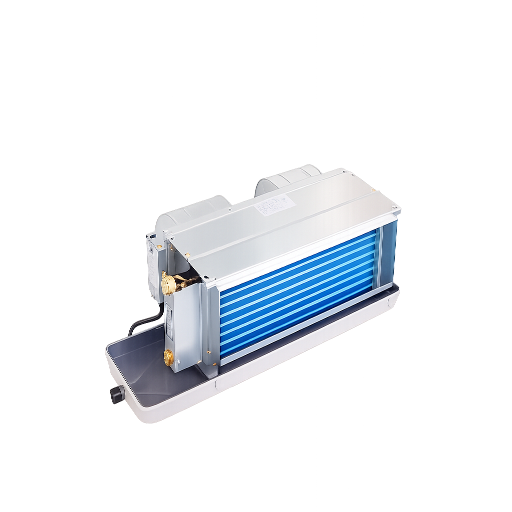
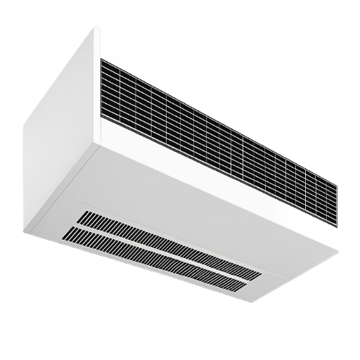
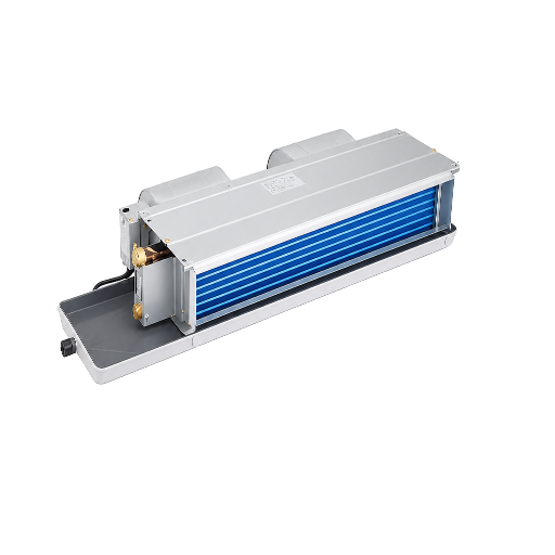
What’s different here: the full nine-model performance matrix sits on this page, not behind a PDF gate.
And: the two-pipe versus four-pipe heating difference is published per model, a number that decides projects and that almost nobody prints.
And: the two-pipe versus four-pipe heating difference is published per model, a number that decides projects and that almost nobody prints.
Why Concealed Fan Coil Unit Selection Fails Above the Ceiling
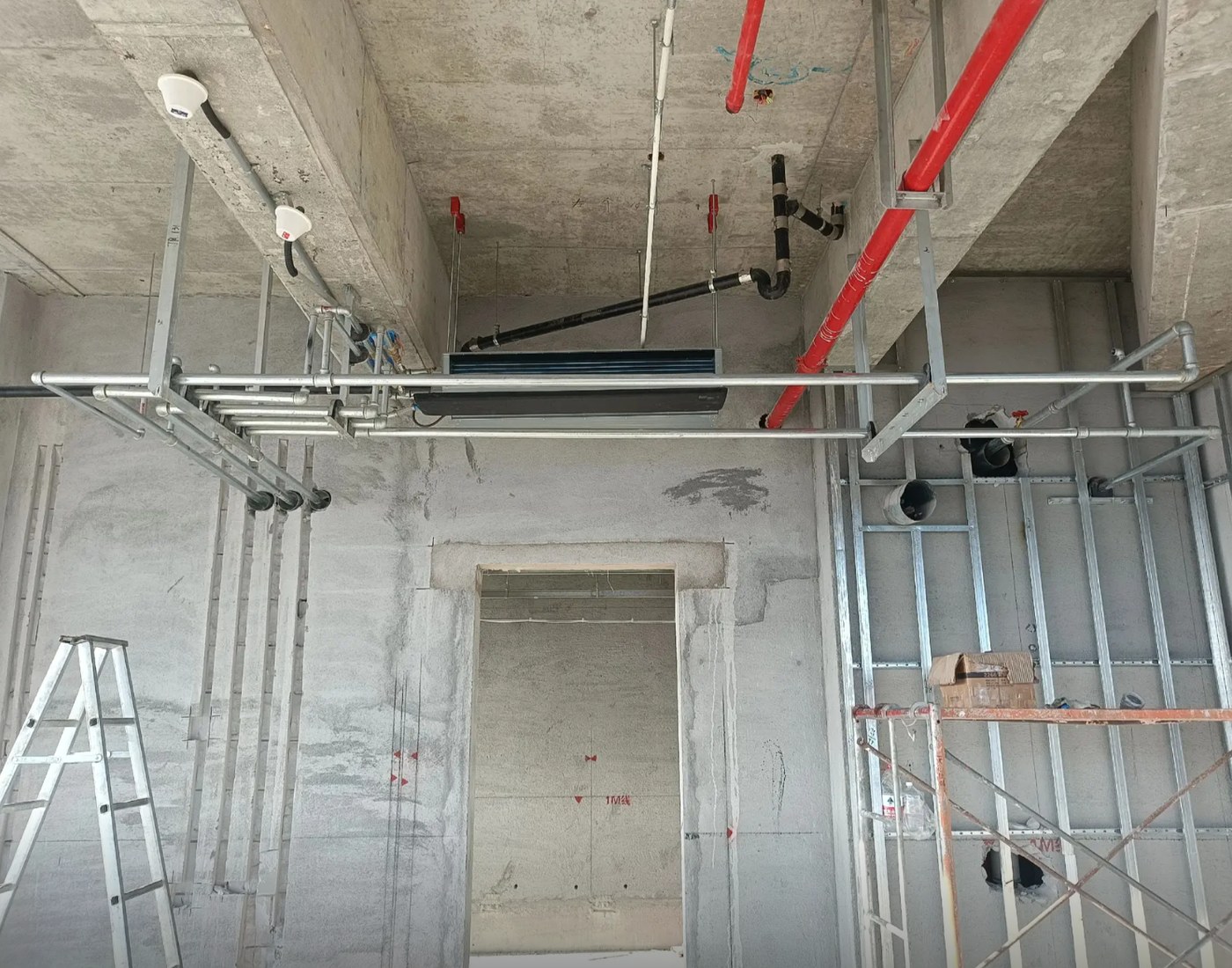
Three numbers decide whether a horizontal fan coil unit survives contact with a real ceiling, and capacity isn’t one of them. Plenum depth, static pressure headroom and condensate fall are what turn a correctly scheduled unit into a change order, and they’re exactly the three that rarely appear anywhere a design engineer can compare them. Nothing about the device itself is difficult: concealed fan coil units (FCUs) pull room air across a chilled-water or hot-water coil and hand the conditioned air back to the space, carrying no compressor and no refrigerant line, because the chiller or boiler does that work elsewhere in the building. That much is settled engineering. Those three numbers are where projects actually fail.
01
Failure one: the unit fits the schedule but not the plenum
Ceiling void gets consumed by structure, sprinkler mains, cable tray and duct crossings, and the fan coil is usually the last item to claim its space. A schedule that lists capacity and airflow but not unit height sends the coordination problem to site, where it becomes a change order. Every KAFP unit is 240 mm high — not a low-profile chassis, and we will not describe it as one — and the installation sheet asks for roughly 300 mm of clear slab-to-ceiling depth, 240 mm of body, 30–50 mm above for the hanger rods and 20–30 mm below for the drain fall. That figure is on this page because it’s the first thing that disqualifies a unit, not the last.
02
Failure two: the fan cannot drive the duct you drew
Concealed units get a short duct run and a return grille, and the external static pressure gets estimated rather than calculated. KAFP performance data is published at 12, 30 and 50 Pa of external static, and the input power roughly doubles across that band on most sizes, a KAFP-05WA draws 44 W at 12 Pa and 61 W at 50 Pa. If your duct run needs more than 50 Pa, the honest answer is that our published envelope stops there and you should talk to us before scheduling the unit rather than after.
03
Failure three: the condensate
The coil surface runs below the room dew point whenever it’s cooling, so water forms, collects in the pan and has to leave. When it doesn’t leave, the float switch stops the unit and the guest calls the front desk. That requirement is unglamorous and specific: DN20 drain, minimum 1% fall, at least 10 mm per metre, run to a floor drain, with a shut-off valve on each water pipe and a motorised two-way valve on the return. Retrofit work is where this bites hardest, because the fall has to be found inside a ceiling void that was never designed to give it up.
A 2025 peer-reviewed field study of roughly 100 economy fan coil units traces most on-site capacity shortfalls to exactly these installation and airflow details rather than to the coil itself. None of the three is exotic. They’re simply the parts of ceiling concealed fan coil unit installation that get settled on site rather than on paper, which is why they end up as variations instead of decisions.
Koven Air engineers check all three against the project drawing before we quote a model, because the alternative is discovering the mistake on site, and an in-house production record covering 400 traceability points is worth nothing if the unit is 40 mm too tall for the void it was sold into. Those three constraints, plenum depth, static pressure headroom, condensate fall, are what the rest of this page answers with numbers rather than adjectives. If you’re mounting units above ceilings, they decide the project before capacity ever does.
KAFP Horizontal Concealed Fan Coil Units, 9 Models, Full Performance Table
The category has settled on a five-axis way of choosing a horizontal unit: capacity, external static pressure, available ceiling space, sound sensitivity, and outside-air capability. It’s a good framework. Where it breaks down is the sound axis, almost always answered with a word rather than a number. Below, every axis gets a value for every model.
01
CAPACITY
Precision cooling/heating load matching.
02
EXT. STATIC PRESSURE
Overcoming systematic ductwork resistance.
03
CEILING SPACE
Ultra-thin structural height constraints.
04
SOUND SENSITIVITY
Decibel-grounded evaluation metrics.
05
OUTSIDE-AIR
Flexible fresh air intake connection architecture.
KAFP two-pipe performance, high fan speed
Source: Koven Air factory selection workbook.
| Model | Airflow High (m³/h) | Airflow Med | Airflow Low | Cooling High (W) | Heating High (W) | Chilled water (kg/h) | Weight (kg) |
|---|---|---|---|---|---|---|---|
| KAFP-02WA | 340 | 246 | 161 | 2,160 | 3,240 | 370 | 14 |
| KAFP-03WA | 510 | 375 | 254 | 3,186 | 4,779 | 550 | 15 |
| KAFP-04WA | 680 | 508 | 345 | 4,176 | 6,264 | 720 | 15 |
| KAFP-05WA ★ | 850 | 654 | 415 | 4,950 | 7,425 | 850 | 18 |
| KAFP-06WA | 1,020 | 775 | 516 | 5,940 | 8,910 | 1020 | 19 |
| KAFP-08WA | 1,360 | 1,034 | 684 | 7,920 | 11,880 | 1,360 | 28 |
| KAFP-10WA | 1,700 | 1,293 | 877 | 9,270 | 13,905 | 1,590 | 30 |
| KAFP-12WA | 2,040 | 1,565 | 1,038 | 11,016 | 16,524 | 1,890 | 33 |
| KAFP-14WA | 2,380 | 1,895 | 1,204 | 12,852 | 19,278 | 2,210 | 36 |
Return duct sizing, per model
Undersized return ductwork is a quiet way to lose both capacity and acoustic performance, because velocity climbs and the fan works against pressure it was never scheduled for. It’s an expensive mistake to fix after the ceiling closes, and unlike a capacity shortfall it rarely shows up until the room is occupied. These are the sections our engineering sheet calls for at 3.5 m/s on high-speed airflow.
| Model | Airflow High (m³/h) | Required area (cm²) | Round duct (mm) | Rectangular duct (mm) |
|---|---|---|---|---|
| KAFP-02WA | 340 | 270 | Φ200 | 200 × 160 |
| KAFP-03WA | 510 | 405 | Φ250 | 250 × 160 |
| KAFP-04WA | 680 | 540 | Φ280 | 250 × 200 |
| KAFP-05WA | 850 | 675 | Φ320 | 320 × 200 |
| KAFP-06WA | 1,020 | 810 | Φ360 | 320 × 250 |
| KAFP-08WA | 1,360 | 1,079 | Φ400 | 400 × 250 |
| KAFP-10WA | 1,700 | 1,349 | Φ450 | 400 × 320 |
| KAFP-12WA | 2,040 | 1,619 | Φ500 | 500 × 320 |
| KAFP-14WA | 2,380 | 1,889 | Φ500 | 500 × 400 |
Re-check against site velocity 2.5–4 m/s. Source: Koven Air.
SCHEMATIC: GEO_01
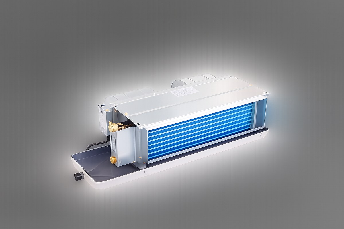
Engineering Geometry & Built Architecture
The three-row coil geometry is a mainstream engineering choice across the category, not a proprietary one — it appears in published designs such as this three-row three-waterway dry-type fan coil patent. Common to every size: a galvanised-steel casing around a double-inlet forward-curved multi-blade centrifugal blower, an AC three-speed motor at 110 V or 220 V, a three-row copper-tube aluminium-fin coil rated to 1.6 MPa, and DN20 connections for supply, return and condensate.
It is a deliberately simple piece of climate-control equipment: one moving assembly, one coil, no compressor. In North American shorthand the range spans roughly 0.6 to 3.6 tons of cooling per unit. The galvanized steel casing and the three-row coil are the two components that decide how reliable the unit stays over a twenty-year plant life, which is why neither is a place we cut costs.
Highlighted above, KAFP-05WA is the size that matters most in hospitality work: a 25–35 m² guest room is generally carried on 3.5–5.0 kW of cooling, which puts KAFP-03WA through KAFP-05WA squarely in that band.
Casing Structure
Galvanised-Steel
Blower Type
Forward-Curved
Motor Specs
AC 3-Speed (110/220V)
Coil Geometry
3-Row Cu-Tube Al-Fin
Pressure Rating
1.6 MPa Max
Interconnect
DN20 Sup/Ret/Drn
Serviceability & Maintenance
A fan coil looks like a low-maintenance device because it’s a simple device, and that reasoning doesn’t survive contact with a building. Filter and condensate pan both live inside the unit, which means somebody has to reach them on a schedule, trade press lists exactly this as the standing drawback of the fan coil approach. So a serviceable-access feature is built into the schedule rather than left to chance: the KAFP install sheet asks for a ceiling access opening of at least 450 × 450 mm on the pipe and control-box side, and at least 300 mm of clear service space on that same side.
Our return grille carries a G4 washable filter rather than a throwaway cartridge, because the realistic maintenance regime in a 200-room hotel is a housekeeping team rinsing a mesh, not a stores order for consumables. Every unit ships completely assembled and fully wired from the factory, which cuts on-site installation time and removes the parts-availability risk of building a coil section in a ceiling void.
System Integration Framework
Zone Control Purpose
Zone control is the reason the device exists at all. Each unit answers one thermostat and one space, which is why the format persists in buildings where the occupants each want to be comfortable on their own terms and disagree with each other about temperature, hotels, wards, dormitories, and the perimeter of any office floor. In practice that’s also what separates this application from a central air handling unit: a fan coil unit vs air handling unit decision is really a decision about how many zones you need to satisfy independently, not about how much air you need to move.
Types of fan coil units differ mainly in where they sit, concealed above a ceiling, cassette in the tile, vertical in a closet, floor-mounted at the perimeter, and the concealed horizontal format wins wherever the ceiling can hide 240 mm and the room can’t spare the floor.
Sizing a specific room and want the numbers in a spreadsheet rather than a web table?
> Full data structure optimized for engineering processing maps.VS
2-PIPE SYS
[ CAP: 100% UTILIZED ]
4-PIPE SYS
[ SPLIT: 3C + 1H ]
Two-Pipe vs Four-Pipe Fan Coil: The 42% Heating Penalty
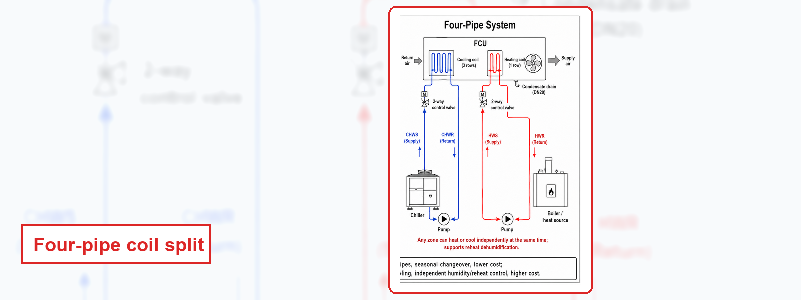
Four-pipe is the more capable system and it heats worse. That’s the trade-off nobody prints, and it’s the one specifiers most often get wrong, unlike a cooling shortfall, a 4,298 W heating gap doesn’t announce itself until the first cold week. Across all nine KAFP sizes, the four-pipe unit delivers between 38% and 44% of the heating output of the same-size two-pipe unit. On a KAFP-05WA that’s 7,425 W dropping to 3,127 W.
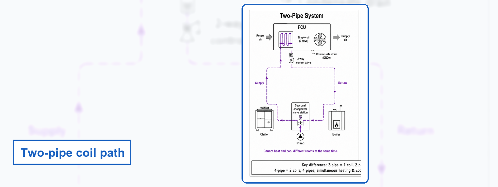
This isn’t a defect and it isn’t specific to Koven Air, it falls straight out of how the two configurations are built, and it catches projects that assume four-pipe is simply the upgrade. Coil geometry is the cause. A two-pipe unit runs hot water through the entire three-row coil. A four-pipe unit keeps the main cooling coil and adds a separate, small heating coil, a 3+1 row arrangement.
ACCESS COMPARISON SHEETOUTPUT_METRICS // ALL_NINE_MODELS
Source: Koven Air factory comparison workbook. High fan speed.
| Model ID | 2-Pipe Heat (W) | 4-Pipe Heat (W) | 4-Pipe as % of 2-Pipe | 2-Pipe Cool (W) | 4-Pipe Cool (W) |
|---|---|---|---|---|---|
| KAFP-02WA | 3,240 | 1,390 | 43% | 2,160 | 2,250 |
| KAFP-03WA | 4,779 | 2,112 | 44% | 3,186 | 3,320 |
| KAFP-04WA | 6,264 | 2,687 | 43% | 4,176 | 4,396 |
| KAFP-05WA | 7,425 | 3,127 | 42% | 4,950 | 5,135 |
| KAFP-06WA | 8,910 | 3,705 | 42% | 5,940 | 6,188 |
| KAFP-08WA | 11,880 | 4,748 | 40% | 7,920 | 8,293 |
| KAFP-10WA | 13,905 | 5,530 | 40% | 9,270 | 9,557 |
| KAFP-12WA | 16,524 | 6,443 | 39% | 11,016 | 10,888 |
| KAFP-14WA | 19,278 | 7,409 | 38% | 12,852 | 13,529 |
REBALANCE_METRICS
Read the cooling columns too, because they carry the second half of the story: four-pipe cooling is marginally higher across the range. So the four-pipe unit isn’t weaker, it has been rebalanced. You’re trading winter output for year-round independence.
APPLICATION_GUIDE
Independent engineering guidance puts four-pipe fan coil systems in large facilities on chilled water, campuses, large residential complexes, large hotels, and anywhere individual room temperature control is genuinely required.
CTRL_LOGIC_IMPACT
Control logic differs as well, and it shows up in the commissioning budget. Four-pipe needs two valves, a thermostat that can call for heating and cooling independently, and interlock logic so the two coils never fight each other across a dead band.
10_QUESTION_EVALUATION_MATRIX
This is the matrix our application engineers actually work from. Answer the left column against your project and the system recommendation falls out.
| Evaluation Parameter | Typical Environment | System Output |
|---|---|---|
| Do different rooms need heating and cooling at the same time? | Hospital wing cooling while the other side heats | 4-PIPE |
| Is the building in a single seasonal mode? | Residential, temperate-climate office | 2-PIPE |
| Is first cost the binding constraint? | Cost-sensitive project | 2-PIPE |
| Is ceiling void or riser space very tight? | Dense services, simple routing | 2-PIPE |
| Is there year-round perimeter heating alongside core cooling? | Large office core plus perimeter | 4-PIPE |
| Do you need precise independent zone control? | Laboratory, high-end hotel, healthcare | 4-PIPE |
| Do you need high heating output from the unit? | Cold climate, single coil sufficient | 2-PIPE (Full coil utilization) |
| Do you need independent humidity control by reheat? | Cleanroom, constant-humidity space | 4-PIPE |
| Is shoulder-season efficiency a priority? | Avoiding changeover waste | 4-PIPE |
| Do you want condenser heat recovery? | Aggressive energy target | 4-PIPE |
WARNING_EXCEPTION
Question seven is the one that gets skipped, and it’s the one this section exists for. If the project is in a cold climate and doesn’t need simultaneous heating and cooling, specifying four-pipe out of habit buys flexibility you won’t use and gives back nearly 60% of your heating capacity to get it.
Sound Pressure by Static Pressure, Published, Not Claimed
A catalogue can be quiet and capable on the same page without being both at the same time. That is not a rhetorical point. A 2025 peer-reviewed field study tested roughly 100 economy fan coil units and then re-tested certified models in an ISO 3745 anechoic chamber. It found cooling capacity landing anywhere from 85.4% to 118.2% of rated capacity, and traced the shortfall to airflow that had been intentionally reduced to meet the NC-40 acoustic criterion (Oh, Scientific Reports, 2025). Its authors call it what it is: a compromise of thermal comfort for acoustic compliance.
Now put that next to the requirement. Hotel guest rooms are designed to NC 30 to 35, five to ten points tighter than a typical office at NC 40, and the standard expects the fan coil, the ductwork and the diffusers to all hit that target together. Units in that study were meeting an office-grade number and still giving capacity back. A guest room asks for more.
Which is why the useful question isn’t “how quiet is it” but “quiet at which airflow, and what capacity was left at that airflow”. Below is The Same-Point Sound Table: the KAFP sound-pressure figures at the same three static-pressure points as the airflow and input-power data. Same unit, same operating points, one table.
The Same-Point Sound Table
KAFP sound pressure and input power at 12 / 30 / 50 Pa external static, high fan speed. Manufacturer-tested A-weighted sound pressure, Koven Air factory laboratory.
| Model | dB(A) @ 12 Pa | dB(A) @ 30 Pa | dB(A) @ 50 Pa | Input W @ 12 Pa | Input W @ 30 Pa | Input W @ 50 Pa | Airflow High (m³/h) |
|---|---|---|---|---|---|---|---|
| KAFP-02WA | 37 | 40 | 42 | 22 | 26 | 29 | 340 |
| KAFP-03WA | 39 | 42 | 44 | 30 | 34 | 40 | 510 |
| KAFP-04WA | 41 | 44 | 46 | 36 | 42 | 49 | 680 |
| KAFP-05WA | 43 | 46 | 47 | 44 | 51 | 61 | 850 |
| KAFP-06WA | 45 | 47 | 49 | 56 | 65 | 80 | 1,020 |
| KAFP-08WA | 46 | 48 | 50 | 78 | 91 | 101 | 1,360 |
| KAFP-10WA | 48 | 50 | 52 | 88 | 101 | 125 | 1,700 |
| KAFP-12WA | 50 | 52 | 54 | 114 | 140 | 173 | 2,040 |
| KAFP-14WA | 52 | 54 | 56 | 139 | 166 | 208 | 2,380 |
What these numbers are, and what they are not
These are A-weighted sound pressure figures from our own factory testing. They’re not octave-band sound power data, and they aren’t an NC rating. An ideal terminal-unit specification asks for discharge and radiated sound power by octave band so that an acoustic consultant can subtract the room and duct attenuation and arrive at NC. We don’t publish octave-band sound power, so you can’t derive an NC value from this table, and we aren’t going to imply that you can.
We’re also not claiming to be quieter than anyone else. No competitor publishes on-page dB figures for us to compare against, which means a comparison would have no basis, and we would rather have no claim than a claim with no basis. What we’re claiming is narrower and checkable: the airflow, the capacity, the input power and the sound pressure on this page all come from the same three operating points. Nothing here was measured at one airflow and printed next to a number taken at another.
Two practical notes fall out of the table, and both matter in the field. First, sound climbs with static pressure on every size, typically five decibels from 12 Pa to 50 Pa, so a duct run you haven’t calculated is an acoustic decision you haven’t made. Unlike a capacity error, this one is expensive to fix after handover: the application is already occupied, and the remedy is ductwork, not a setting. Second, our engineering sheet asks for duct velocity in the 2.5–4 m/s band and says plainly: take the lower value in noise-sensitive rooms. That’s the trade-off the study describes, stated openly rather than buried in a derated airflow, the catch being that the quieter number you were shown may simply be the lower-airflow number.
Commercial HVAC Installations: Hotel Rooms, Financial-Tower Halls, Conference Rooms
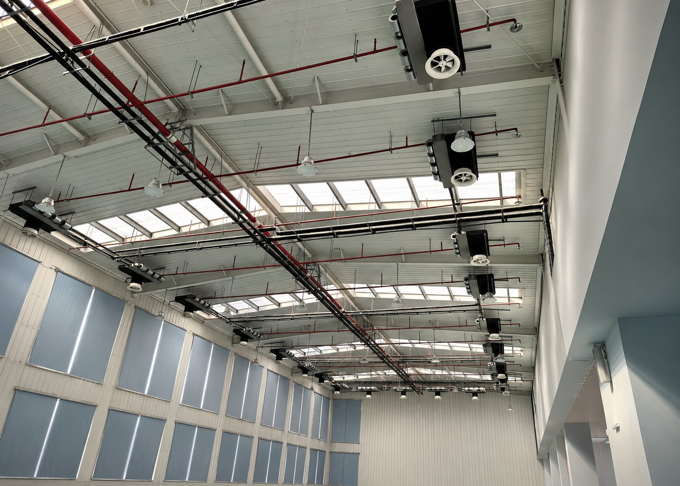
Chilled-water fan coils on a central plant remain the default for hotels above roughly 100 rooms, for reasons that have nothing to do with fashion: long plant life, straightforward field maintenance, flexible indoor installation, and efficiency that scales from a boutique property to a data-hall floor. KAFP concealed units are built for that job, and for the buildings that behave like it.
Below that threshold the honest answer is often different. A 4 pipe fan coil vs VRF comparison usually turns on size rather than preference: independent design guidance puts VRF ahead for boutique properties under about 100 rooms, where avoiding a plant room, a cooling tower and chilled-water pipework outweighs the benefits, and puts chilled water ahead above it, where 20-plus year plant life and lower operating cost win.
Hotel guest rooms
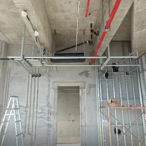
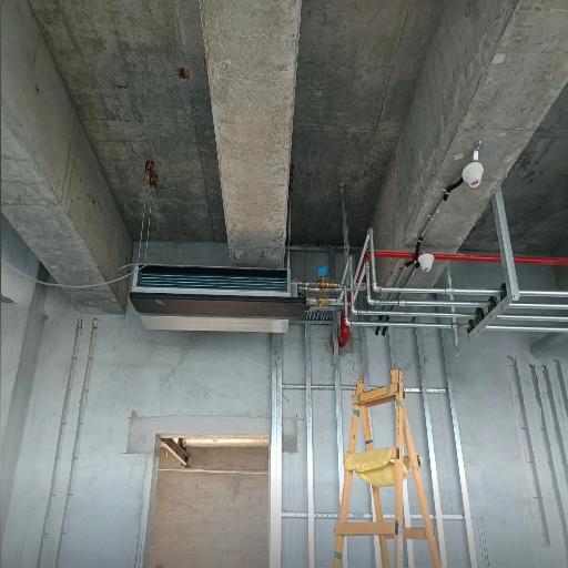
SYS.01 ACTIVEGuest floors are the hardest acoustic environment a fan coil sees and the easiest place to under-coordinate, and in practice the failure is always the same: a unit that met the schedule and missed the room. Academic acoustic analysis of guest-room fan coils reaches the same conclusion by computing sound power against the target room level. Each unit sits above the entry corridor or the bathroom bulkhead and supplies the sleeping area directly. Room loads in the 3.5–5.0 kW band land on KAFP-03WA to KAFP-05WA, which at 12 Pa external static sit at 39, 41 and 43 dB(A) respectively. Our installed work covers the full sequence, rough-in, pipe and drain detailing, ceiling closure and finished room.
ACCESS FILE
Hotel
Guest Rooms
KAFP-01
Financial-tower halls & offices
SYS.02 ACTIVEOpen halls and conference spaces change the problem: longer duct runs, higher airflow, and an acoustic target set by speech rather than sleep. Larger sizes carry these, KAFP-08WA through KAFP-14WA span 1,360 to 2,380 m³/h, and the return duct table above is the part that decides whether that airflow arrives at the velocity you designed for. Corridors, large meeting rooms and lobby zones in a financial tower have run on this range, with aesthetic integration handled by the ceiling contractor rather than by the unit.
ACCESS FILE
Financial
Tower Halls
KAFP-02
Where it earns its place
SYS.03 ACTIVEUnlike a marketing claim, an installed reference can be walked. Koven Air production covers the full KAFP range in-house, and every unit in these applications left the factory only after the 36-item inspection and the 24 hour aging test. Independent guidance puts four-pipe fan coil systems in large facilities on chilled water, in spaces with high sensible heat ratios, and where individual room control is genuinely required, large hotels, campuses, residential complexes. Koven Air equipment runs in hospitals, business centres, industrial parks, office buildings, gymnasiums, libraries, schools, airports, data centres and computer rooms across 35 countries.
ACCESS FILE
Where Format
Earns Place
KAFP-03
Build Standards, Factory Process & What We Do Not Claim
We do not hold AHRI 440 certification
Stating that plainly is more useful to you than letting you find out at the submittal stage. AHRI Standard 440 is the performance rating standard for room fan coils, it fixes the test method, the rating requirements and the minimum data a manufacturer must publish. It matters because ASHRAE 90.1 references it directly: hydronic fan-coil coils are expected to be rated in accordance with AHRI 440. It’s a rating methodology referenced by an energy standard, not a badge.
So if your specification requires AHRI 440 certified equipment as a hard gate, we don’t meet it today, and no amount of describing our factory changes that. What follows is what we do have and can evidence. Judge it on its own terms.
What is actually behind the unit
20,000m² Mfg floor
18Standard proc.
23Sheet-metal
400Traceability
36Inspection pts
24hAging test
2007First chiller
35Countries
Process Facts vs. Claims
Here’s the honest version of what that buys you and what it doesn’t. Unlike a certification mark, none of it’s third-party verified, and pretending otherwise is exactly the mistake that gets a supplier removed from a bid list at the audit stage rather than the quotation stage. Those are process facts rather than performance claims, and the distinction is the point.
A 400-point traceability record tells you that when a unit misbehaves on site we can find out which coil, which shift and which batch, it doesn’t tell you the unit hits its rated capacity, and we aren’t going to let it stand in for that. We run our own chiller and heat-pump test laboratory, and every unit ships only after it passes factory inspection and the 24-hour aging test.
VIEW 01 / 06
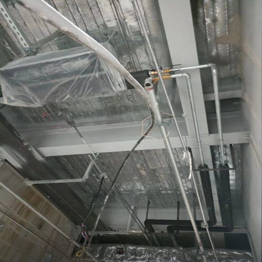
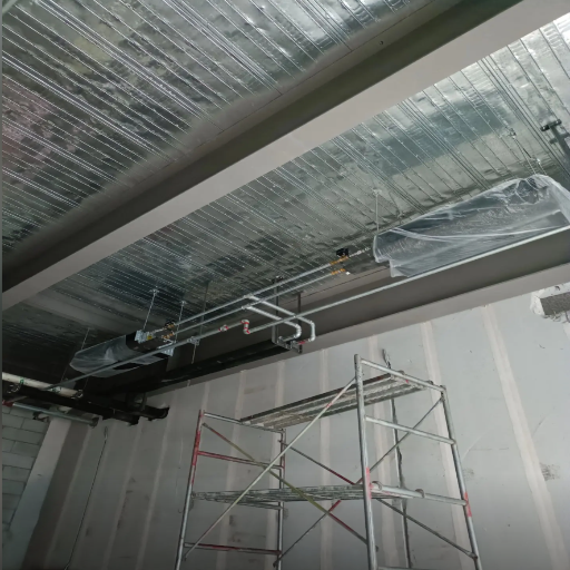
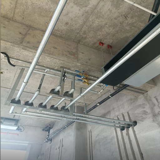
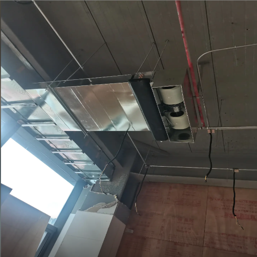
The standards this range is designed against
Design basis follows ASHRAE Handbook, HVAC Systems and GB 50736 for the terminal design itself; GB 50189, ASHRAE 90.1 and IECC set the energy envelope the equipment has to live inside; SMACNA and GB 50243 govern the ductwork and the installation.
For the direction the category is moving, ultra-thin bodies and higher-efficiency coils, see published work such as this ultra-thin fan coil patent; the KAFP range is deliberately a conventional 240 mm chassis, not an ultra-thin one. Every unit carries a three-row copper-tube aluminium-fin coil rated to 1.6 MPa maximum working pressure, and the install sheet requires chilled-water pipe and duct to be insulated against condensation as a matter of course, not as an option.
Horizontal Fan Coil Unit Engineering Tools
KAFP Concealed Fan Coil Selector
Enter the room cooling load, the external static pressure your duct run imposes, and your acoustic target. The tool returns the KAFP models that meet the load, with the sound pressure and input power at your static-pressure point — the same three numbers that decide the selection.
Launch SelectorTwo-Pipe vs Four-Pipe: Heating Reality Check
Four-pipe gives you simultaneous heating and cooling. What the datasheets rarely put side by side is what it costs the heating coil. Pick a model and your climate, and see the real numbers — then get a recommendation, not a default.
Compare ConfigurationsReturn Duct Sizer & Ceiling Void Check
The three things that turn a scheduled fan coil into a site change order: the return duct is undersized, the ceiling void is too shallow, or the condensate cannot fall. Pick a model and check all three before the ceiling closes.
Verify Constraints
Information
Fan Coil Unit FAQ
Technical specifications, installation guidelines, and system comparisons for Koven Air concealed units.
Room load first, then static pressure, then the acoustic target, in that order. A 25–35 m² guest room usually needs 3.5–5.0 kW, which lands on KAFP-03WA to KAFP-05WA. Read the sound table at the static pressure your duct actually imposes, not the one you hoped for — published field research shows why the hoped-for number and the real one diverge.
Two-pipe runs one coil on a single supply-and-return pair, switching the whole building between chilled and hot water seasonally. Four-pipe keeps separate cooling and heating circuits so any zone can heat while another cools. What’s rarely published: four-pipe uses an independent small heating coil in a 3+1 row arrangement instead of running hot water through the full coil, so its heating output is 38–44% of the same-size two-pipe unit, 3,127 W against 7,425 W on a KAFP-05WA. Full nine-model table above.
Neither answer is safe as a generalisation, and the reason matters more than the answer. A 2025 peer-reviewed field study found certified units delivering 85.4–118.2% of rated cooling capacity because airflow had been reduced to hit an acoustic target. A quieter published figure, in other words, may simply be a lower-airflow figure wearing a different hat. So comparing two decibel numbers tells you almost nothing unless you also know the airflow and the capacity that stood behind each one. Compare sound and capacity at the same operating point, or don’t compare at all. For our concealed range that pairing is in a single table above, which is the whole reason it’s laid out that way. One structural difference does hold generally: a ducted unit lets you put attenuation in the duct run, and a cassette sitting in the ceiling tile discharges straight into the room with nowhere to hide. That’s a design option, not a decibel claim, and if your project has a hard NC target, the honest route is an acoustic consultant working from octave-band sound power, which neither we nor most of this category publish.
No. Koven Air doesn’t currently hold AHRI 440 certification, and we would rather you know now than at submittal. AHRI 440 is the room fan coil performance rating standard that ASHRAE 90.1 references as the rating basis, so if your specification makes it a hard gate we don’t clear it. What we do have is our own chiller and heat-pump test laboratory, 36 factory inspection items, a 24-hour aging test on every unit and 400 process traceability points, and the published data on this page, at stated operating points, for you to check.
Yes, a concealed unit sits above the ceiling and needs supply and return connected through grilles or short duct. Our published envelope runs to 50 Pa external static, and the data is given at 12, 30 and 50 Pa so you can see what changes across that band: on a KAFP-05WA, input power goes 44 W to 61 W and sound pressure goes 43 to 47 dB(A). Size the return from the duct table above at 3.5 m/s and re-check against the 2.5–4 m/s band on site. If your run needs more than 50 Pa, ask us before you schedule it.
Yes, and we would rather do it before you schedule the unit than after. Send the room loads, the available plenum depth, the duct run and the acoustic target, and our engineering team will return a model-by-model selection with the specific static-pressure column marked, including the case where the answer is that no KAFP size fits your void. Request a quote or a selection check →
Maintenance access, and it’s the one the format can’t design away. Filter and condensate pan both sit inside the unit above a ceiling, so somebody has to get to them on a schedule, trade press lists exactly this as the standing drawback of the approach. A fan coil also puts a fan in every zone, so it uses more fan energy than a passive terminal. Our answer is to make the access realistic rather than to deny the problem: a G4 washable filter on the return grille, an access opening of at least 450 × 450 mm, and at least 300 mm of clear service space on the pipe side.


![Commercial Rooftop Unit Guide: Types, Sizing & Costs [2026]](https://kovenair.com/wp-content/uploads/2026/07/commercial-rooftop-unit-guide-featured-2-150x150.png)