
Get in Touch with Koven Air Company

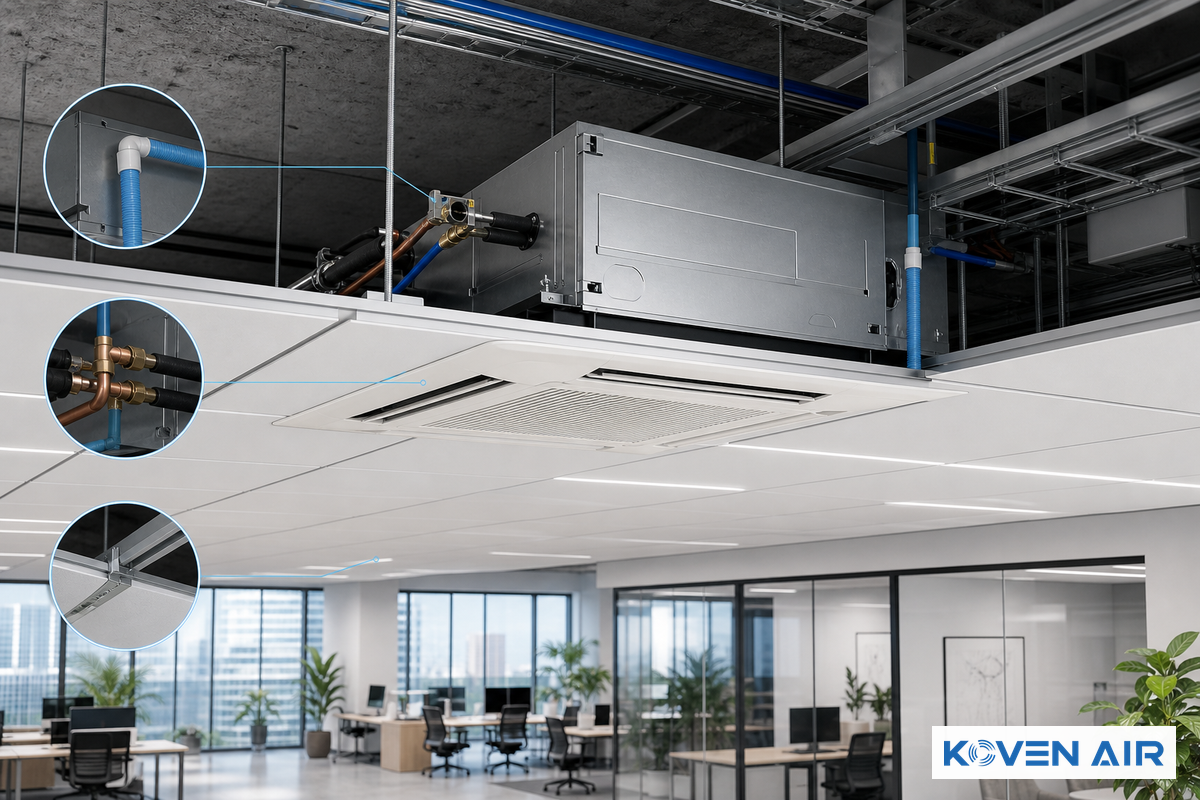
A commercial cassette air conditioner is a ceiling-recessed HVAC terminal that distributes conditioned air through a flush grille. The name covers two different systems: DX/VRF units connected by refrigerant piping and hydronic fan coil units connected to a central chilled- or hot-water plant. This guide explains how to specify either path.
Quick Specs: Commercial Cassette Air Conditioner
| Capacity selection | Vendor/model-specific; size from the room heat-load calculation, not floor area alone |
| Discharge patterns | 1-way, 2-way, 3-way, 4-way, round-flow |
| Two core technology paths | DX/VRF (refrigerant) vs. hydronic FCU (chilled/hot water) |
| Ceiling-void requirement | Model-specific cabinet depth plus service, pipework and condensate clearance |
| Efficiency test standard (US) | AHRI 210/240 — SEER2/EER2/HSPF2 metrics, effective Jan 1, 2023 |
| 2026 compliance watch item | Above-700-GWP VRF: EPA installation windows depend on component and permit dates; verify the applicable sector before ordering |
A commercial cassette air conditioner mounts flush into a suspended ceiling and throws air outward through the room from one, two, three, or four sides instead of through ducted registers. It’s the format facilities teams reach for when floor space is at a premium and the ceiling grid still needs to look clean. Two mechanically unrelated technologies both get sold under this exact name and end up on very different specification sheets: direct-expansion/variable-refrigerant-flow (DX/VRF) cassette units that pump refrigerant to an outdoor condenser, and hydronic cassette fan coil units (FCU) that circulate chilled or hot water from a central plant. This guide compares both paths honestly, covers sizing, installation, and maintenance, and points out where each format earns its keep, including where Koven Air’s chilled-water cassette FCU line fits, and where it doesn’t.
Ceiling-recessed by design, a commercial cassette air conditioner uses either DX/VRF refrigerant or a hydronic FCU water circuit and discharges air in 1 to 4 directions from a flush ceiling grille. Capacity and cabinet depth vary by product series, so selection starts with a room heat-load calculation and the approved submittal drawing.
Key Takeaways
- Two unrelated technologies share the name “cassette AC” — DX/VRF (refrigerant) and hydronic FCU (chilled water). Confirm which one a spec sheet actually describes before comparing prices.
- Cassette heads span a wide capacity range; sizing by floor-area rule of thumb alone can oversize equipment-dense rooms, so use a room-by-room heat-load calculation.
- EPA’s HFC transition schedule makes refrigerant, manufacturing/import, installation and building-permit dates separate procurement checks for US VRF projects.
- Ceiling cassettes don’t bring in outside air on their own, ventilation still needs a dedicated outdoor air system (DOAS) sized separately.
- Ceiling void depth, not tonnage, is usually the first constraint that rules a cassette format out entirely.
What Is a Commercial Cassette Air Conditioner?
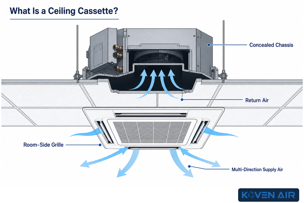
Mounted inside a suspended ceiling grid, a commercial cassette air conditioner is an HVAC terminal unit that discharges conditioned air outward through the room from one to four sides, rather than downward through a single register the way a typical split-system wall head does. Only a slim decorative panel, usually matching a standard 600×600 mm or 2×2 ft grid module, is visible from below, since the equipment housing sits above the ceiling tile.
Return air is usually pulled through a central grille on the same panel, so no separate return duct is needed on most four-way models. Condensate is carried away either by gravity, where the ceiling void allows enough fall, or by a small internal pump where it doesn’t.
Coverage pattern means how many sides the unit throws air on. The practical cassette configuration taxonomy includes 1-way units that send air in a single direction, 2-way units that cover two sides, 3-way units that cover three, and 4-way units that discharge on all four sides, plus round-flow/dual-vane variants that blend the four-way pattern into a continuous circular sweep. Commercial buildings choose this format over fully ducted air handlers for a straightforward reason: there’s no ductwork run to fight for space in a tight plenum, air distribution stays even throughout open floor plans, and the finished look is discreet enough to sit in a lobby or executive office without looking like mechanical equipment.
The phrase “cassette air conditioner” by itself says nothing about how the unit is actually cooled, and that ambiguity causes real specification mistakes. A DX/VRF cassette has an indoor coil connected by refrigerant piping to an outdoor condensing unit; the refrigerant itself carries the heat. In light commercial catalogs, the same ceiling-mounted cassette may be described as a ductless mini split air conditioner or cassette split system. A hydronic cassette fan coil unit has an indoor coil connected by insulated pipework to a central chiller or boiler, circulating chilled or hot water instead of refrigerant. Koven Air, which manufactures only the hydronic FCU side of this category, doesn’t build or sell DX/VRF cassette equipment. That distinction is worth confirming on any quote before assuming a “cassette AC” line item means the same thing in two supplier proposals.
Advantages of the cassette format
- Frees floor and wall space entirely
- Even, multi-directional air throw throughout open-plan rooms
- Low visual profile, flush with the ceiling tile
- Return air is usually integrated into the central grille on four-way models
- Works with either DX/VRF or hydronic plant types
Limitations of the cassette format
- Requires adequate ceiling void for the cabinet, pipework, drainage and service access
- Harder to service than a wall-mounted unit because access is through the dropped ceiling
- Directional throw can create dead zones behind panels or tall features
- Still needs a separate outdoor-air ventilation path (DOAS)
- Hydronic models require a connection to the building’s central plant
How Ceiling Cassette Systems Work: DX/VRF vs. Chilled-Water Hydronic FCU
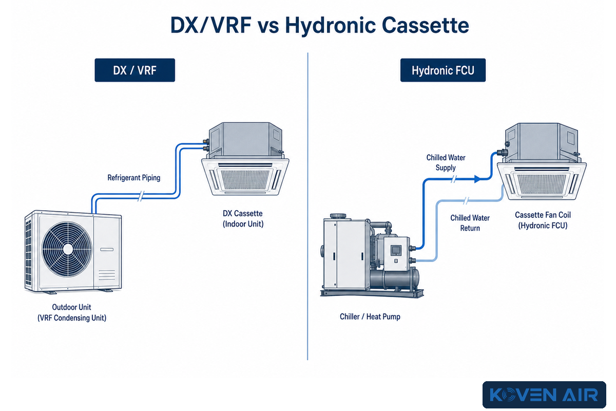
Two mechanically different cooling loops get installed inside the same cassette housing, and which one a project uses determines almost everything else about it: refrigerant charge and permitting exposure for DX/VRF, or hydraulic balancing and central-plant sizing for hydronic FCU. The cassette housing and diffuser design are largely shared engineering between the two paths; the coil, piping, and outdoor equipment behind that housing aren’t.
DX/VRF Cassette Systems
A DX/VRF cassette carries refrigerant, typically R-410A or the lower-GWP R-32 on newer models, between an indoor coil and an outdoor condensing unit or VRF branch controller, with the compressor doing its work outside the occupied space. Variable refrigerant flow (VRF) systems let a single outdoor module serve many indoor cassette heads, each modulating independently, which is what makes DX/VRF the common choice for phased tenant fit-outs where zones get added over time. Internal diffuser geometry matters more than it looks: one U.S. patent covering a cassette-type air conditioner deflector describes angling the deflector so air flows smoothly toward the exhaust ports “without a secondary air-flow” — the kind of detail that separates a unit that throws air evenly from one that creates a draft along one edge of the panel.
Hydronic Cassette FCU, Koven’s Line
A hydronic cassette FCU replaces the refrigerant coil with a chilled-water (or, on 2-pipe/4-pipe systems, hot-water) coil, connected by insulated pipe to a central chiller or boiler plant rather than to a dedicated outdoor unit. Two-pipe layouts carry either chilled or hot water depending on the season; four-pipe layouts carry both simultaneously, letting different zones heat and cool concurrently off the same central plant. There’s no refrigerant at the zone level, which sidesteps refrigerant-charge code limits entirely, a point covered in more detail in the comparison matrix below. Cassette housing geometry still matters here too: a related U.S. patent for a ceiling cassette air conditioner housing describes a bell-mouth intake shape with a bottom opening and defined outer circumferential surface, a design detail aimed at keeping intake airflow uniform over the coil face.
Engineering note: For a hydronic cassette FCU, coil selection, drain-pan design and installation quality matter more than the ceiling panel’s appearance. Treat those items as submittal checks rather than assuming every recessed unit performs alike.
Koven Air’s current cassette fan coil unit page identifies the product as hydronic and states that the room terminal doesn’t carry refrigerant. For procurement, ask the supplier to attach coil pressure/leak-test records, drain-pan functional-test results and unit traceability to the submittal package; those project records are more useful than relying on unsourced factory-count or generic aging-test figures.
| Dimension | DX/VRF Cassette | Hydronic Cassette FCU | Limitations / Not suitable for |
|---|---|---|---|
| Cooling/heating medium | Refrigerant (R-410A/R-32) to each indoor unit | Chilled/hot water from a central plant | Both water and refrigerant leaks can remain concealed above a ceiling; detection and isolation provisions differ by project |
| Outdoor equipment | Condensing unit or VRF module per zone group | Central chiller/boiler + tower or air-cooled condenser | DX/VRF needs per-zone outdoor siting/noise clearance; hydronic needs a plant room with spare capacity |
| Indoor, outdoor piping | Refrigerant lineset — licensed handling required | Insulated hydronic pipe — standard plumbing trades | Allowable refrigerant line lengths and sizing are manufacturer-specific; long hydronic runs require hydraulic balancing |
| Zone-level code exposure | ASHRAE 15 refrigerant-charge limits apply | No refrigerant at the zone level | DX/VRF can be ruled out in small occupied rooms above an ASHRAE 15 concentration limit |
| Simultaneous heat + cool | Available on model-specific heat-recovery VRF layouts with added branch hardware and controls | Native on a 4-pipe layout | 2-pipe hydronic cannot heat one zone while cooling another in the same season |
| Capacity selection | Limited by the approved indoor/outdoor combination and branch design | Limited by coil, water temperatures, flow and central-plant capacity | Compare published capacity at the actual entering conditions, not nominal labels alone |
| Central plant dependency | None — self-contained per outdoor unit | Full — only as good as the chiller/boiler behind it | Hydronic FCU is not viable without adequate central plant capacity in place or planned |
| Best-fit building profile | Standalone buildings, phased tenant fit-outs | Campuses/new-builds with a central plant (hospitals, hotels, high-rises) | DX/VRF branch limits are manufacturer-specific; verify indoor-unit count, combination ratio and controller topology |
| Refrigerant / GWP compliance | EPA restrictions and sell-through windows vary by VRF sector, refrigerant GWP, component date and permit status | No refrigerant in the hydronic room loop | Confirm the exact condensing-unit refrigerant and applicable EPA transition dates before ordering |
Types of Cassette Units: 1-Way to 4-Way, Round Flow, and Multi-Zone Variants
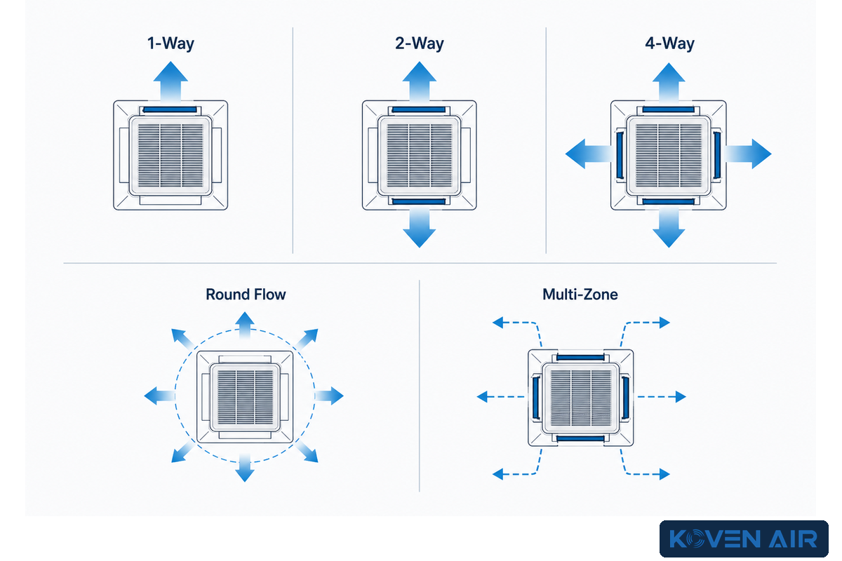
1-way, 2-way, 3-way, and 4-way describe how many directions a cassette air handler throws air. These are the four base discharge patterns manufacturers build around the same recessed housing, with fan speed, vane control, and multi-zone grouping layered on top of any of them. Picking the wrong pattern for a room’s shape is one of the more common and most avoidable specification mistakes on a cassette project.
4-Way and Dual-Vane / Round-Flow Cassettes
A standard 4-way cassette discharges air on all four sides and suits open-plan offices and roughly square-to-rectangular rooms where the unit can sit centrally with clearance on every side. Round-flow (dual-vane) variants blend that same four-direction coverage into one continuous circular sweep through a circular diffuser plate, which can reduce the draft complaints that a hard-edged 4-way pattern creates in seating areas. Restaurants, lobbies, and open lounges are where this variant shows up most. The bell-mouth intake geometry referenced in the housing patent cited above is part of why a well-engineered round-flow unit keeps intake airflow even over the coil face rather than pulling unevenly from one side.
Fan Speed, Vane Control, and Zoning
Inverter (variable-speed) cassette units modulate compressor and fan output to match the actual load rather than cycling fully on and off, which gives steadier humidity control and quieter operation. That’s a meaningful factor in offices and classrooms where compressor cycling noise is noticeable. Non-inverter (fixed-speed) units cost less upfront and remain a reasonable choice for spaces with fairly constant, predictable loads. Auto-swing vanes adjust discharge angle automatically through the day; multi-zone branch controllers group several cassette heads, of any discharge pattern above, onto one outdoor unit (DX/VRF) or one hydronic loop (FCU), letting a floor with several small rooms run independent thermostats off shared central equipment.
| Type | Best-fit room shape | Sizing basis | Limitations / Not suitable for |
|---|---|---|---|
| 1-way cassette | Narrow rooms, corridors, perimeter zones | Room load plus throw distance along one axis | Poor coverage in open floor plans — needs several units for a wide room |
| 2-way (corner) cassette | Corner rooms, L-shaped spaces | Room load plus the two active discharge paths | Not efficient in square or centrally-planned rooms |
| 2-way (opposite/linear) cassette | Long rectangular rooms, retail aisles | Room load plus opposite-direction throw | Leaves the two un-served walls comparatively under-conditioned |
| 3-way cassette | Rooms with one wall obstructed (windows, fixed furniture) | Room load plus obstruction and throw review | Model availability varies by OEM, so confirm the configuration and lead time early |
| 4-way standard cassette | Open-plan offices, square/rectangular rooms | Room load plus four-side throw and partition review | Needs full 4-side clearance — not for rooms with partitions close to the unit |
| 4-way compact (600×600 mm grid) | 2×2 ft drop-ceiling grids, retrofits | Room load constrained by the selected compact model’s airflow | Lower maximum airflow than a full-size 4-way model |
| Round-flow / dual-vane cassette | Open seating, restaurants, lobbies sensitive to draft | Room load plus occupied-zone draft review | Check model-specific price, controls and replacement-panel availability |
| High-static 4-way (short ducted return) | Rooms needing the return grille relocated | Room load plus fan performance at the actual external static pressure | Added static pressure cuts airflow unless the fan is upsized |
| Multi-zone branch grouping | Floors with several small zones needing separate thermostats | Varies with branch capacity | Oversubscribing a branch beyond its rated capacity starves peak-load zones |
Cassette AC vs. Other HVAC System Types
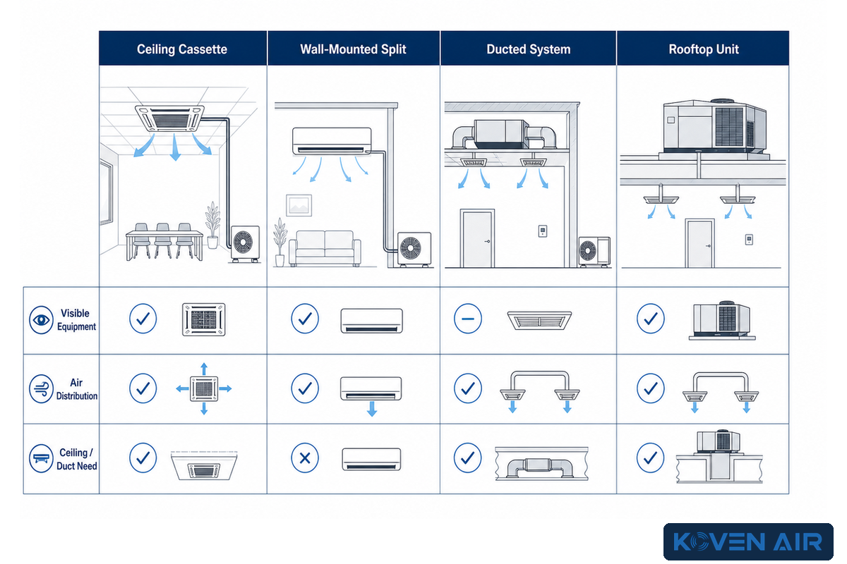
Ceiling cassettes compete for the same commercial floor space as wall-mounted mini-splits, fully ducted concealed air handlers, and rooftop package units. The cassette format’s recessed layout changes the installation trade-off: the deciding factors are usually ceiling-void depth and how the space is already zoned, not raw efficiency, which tends to be broadly comparable among formats once the technology (DX/VRF vs. hydronic) is held constant.
Ceiling cassette
- Recessed into the ceiling grid; required void depth is model-specific
- Even multi-directional air throw
- Return air integrated on 4-way models
- Filter access from below the ceiling tile
Ducted concealed unit
- Sits fully above the ceiling, ducted to multiple registers
- Flexible register placement away from the unit
- Return duct usually separate from supply
- Filter access usually at the unit — often needs a ceiling-tile removal
Wall-mounted mini-splits remain the easiest retrofit of the three because they require no ceiling work, but the visible indoor unit takes wall space and reads as residential rather than commercial in a lobby or client-facing room. Rooftop package units (RTUs) put nearly all the equipment on the roof, which suits one large open floor well, but still need ductwork dropped through the ceiling to distribute air, and the roof needs enough structural capacity for the added weight. Either DX/VRF or hydronic FCU can technically sit behind any of these format choices, but hydronic FCU only makes economic sense where a chilled-water riser already exists or is already budgeted into the building.
Sizing and Specification: BTU, Airflow, and Capacity Selection
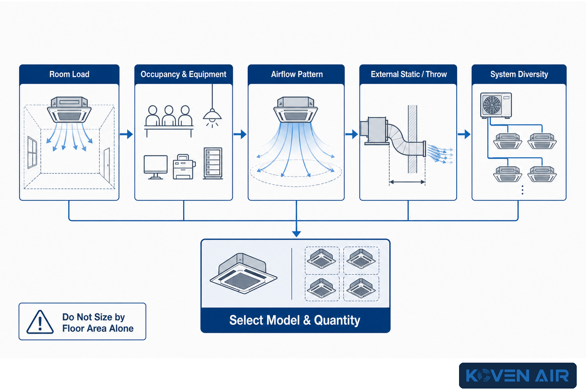
Correct cassette sizing starts from a real room cooling-load calculation, not a floor-area rule of thumb. Two rooms with the same floor area can need very different capacities when one carries dense IT equipment or commercial cooking loads and the other is a lightly occupied office. Occupancy density, equipment heat, glazing and solar orientation, ceiling height, envelope performance and local design weather all move the answer.
Engineering Note: Floor-area shortcuts hide the variables that usually drive a commercial load: people, plug loads, process heat, glass exposure, ventilation air and operating schedule. Run (or request) a room-by-room load calculation before locking in capacity; use the resulting sensible and latent loads to check both coil output and airflow.
Start the selection workflow by calculating the room’s sensible and latent design loads. Shortlist cassette models whose published capacity covers both at the project’s entering-air and water/refrigerant conditions, then compare the required supply airflow with each model’s fan table. Check the throw pattern against partitions and occupied zones before finalizing the model, because two units with similar nominal capacity can deliver different airflow and sound levels at the actual operating point.
Reading the efficiency rating on a spec sheet has its own trap: the applicable metric depends on the equipment class. For U.S. residential and light-commercial DX equipment covered by AHRI 210/240, the Department of Energy’s updated test procedure uses SEER2, EER2 and HSPF2 instead of the older SEER, EER and HSPF figures. Larger commercial outdoor equipment may be rated with other metrics, including IEER or COP. Compare ratings only within the same metric and equipment class rather than treating every cassette system as if one efficiency scale applies.
Illustrative Scenario: Turning Room Data into a Cassette Shortlist
This worked example shows the input structure a project team can use to compare DX/VRF and hydronic candidates. It is not a design calculation or a Koven project record. Every value below is hypothetical and must be replaced by the room-load calculation, selected-model submittal, electrical design and installation manual before procurement.
| Selection input | Hypothetical value | Decision use |
|---|---|---|
| Room and ceiling envelope | 240 m² floor area; 3.2 m ceiling; 420 mm clear void | Screens cabinet depth, throw pattern and service access |
| Calculated room load | 24 kW sensible; 6 kW latent; 30 kW total | Checks capacity at the actual rating conditions |
| Air distribution target | 3,200 m3/h total; compare 800 m3/h, 1,000 m3/h and 1,200 m3/h fan points | Tests airflow, sound and the number of indoor units |
| Operating schedule | 10 hours/day, 5 days/week; 10% reserve only if the load calculation allows it | Prevents an arbitrary safety factor from driving oversizing |
| Hydronic comparison point | 12 L/min coil flow; 45 m plant-to-unit pipe route | Frames pump head, valve and plant-capacity checks |
| DX comparison point | 45 m refrigerant route; 230 V branch-circuit placeholder | Flags manufacturer piping limits and electrical coordination |
| Service envelope | 600 mm frontal access; 450 mm side clearance; 600 mm × 600 mm access panel | Confirms that filters, valves and drain components remain reachable |
| Condensate route | 12 m run; 750 mm lift; 15 L/min pump-rating placeholder | Checks gravity fall or pump selection against the installation manual |
| Commissioning tolerance | 2 hours for the illustrative drain test; 5% airflow-deviation flag | Creates a documented handover check instead of a visual signoff |
| Initial inspection plan | 1 month filter check; 3 months first drain reinspection | Establishes a starting point to be replaced by the manufacturer’s schedule and site history |
Installation, Ceiling Clearance, and Condensate Drainage Requirements
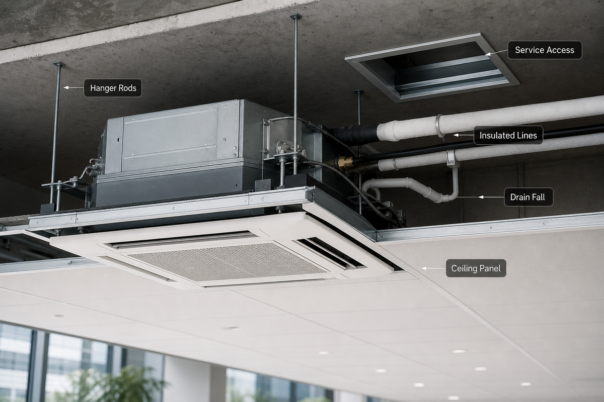
A cassette unit won’t fit if there isn’t space for the cabinet plus the suspension hangers, drainage slope, pipes, and servicing within the ceiling void. And as cabinet dimensions vary noticeably among manufacturers and by unit capacity, the appropriate, factory-approved submittal drawing rather than a dimension in inches serves as the very first gate in selecting technology or tonnage.
Ceiling Depth, Structural Support, and Humidity
Beyond the raw depth number, the unit needs to hang from real ceiling structure, such as joists or a dedicated support frame, rather than from the light-gauge suspended grid that carries the tiles. The ceiling void itself also needs to stay dry: an uninsulated cold surface (refrigerant lineset, chilled-water pipe, or the cassette housing itself) inside a humid void can sweat and stain the tile below it just as readily as a drainage failure can. A 2014 NIST study on underperforming HVAC equipment found leaky ductwork the single most common fault category in HVAC systems generally, with refrigerant undercharge and incorrectly sized airflow close behind. It’s a general finding, not a cassette-specific result, but it’s a useful reminder that a correctly selected cassette still underperforms when the surrounding ductwork, refrigerant charge, or airflow path is wrong.
Condensate Drain and Pump Requirements
Gravity condensate piping needs continuous fall that meets the selected model’s installation manual; where the ceiling void doesn’t allow that fall, a condensate pump lifts the water to a suitable drain instead. Improper slope, priming or pump-lift selection can show up later as ceiling staining or an active leak even when the system looked dry at commissioning.
Do
- Level the drain line at the manufacturer’s stated minimum slope
- Install a secondary drain pan or float switch above finished space
- Pour-test the condensate system before the ceiling closes up
- Verify the pump’s lift height against the actual vertical rise
Don’t
- Rely on gravity alone in a ceiling void that’s genuinely level
- Tie the condensate line into a sanitary drain with no air gap
- Skip the pour test because the unit “looks level” by eye
- Ignore standing water in the pan at commissioning
Ventilation Is a Separate Obligation, Why Cassette/VRF Terminals Need a DOAS
A cassette AC, DX/VRF or hydronic, conditions air that’s already in the room; it doesn’t bring in outside air on its own. That job falls to a dedicated outdoor air system (DOAS), sized separately under ASHRAE 62.1. As one HVAC trade publication puts it, VRF terminals “aren’t purpose-built for ventilation.” Ventilation requirements are calculated independently of the cooling or heating load; that’s why a DOAS gets specified as a companion system rather than an afterthought on a cassette-based project. A building with a hydronic plant may route the DOAS coil onto the same chilled-water loop feeding Koven’s chilled-water cassette fan coil unit range, subject to plant capacity and design review.
Where Commercial Cassette Systems Make Sense
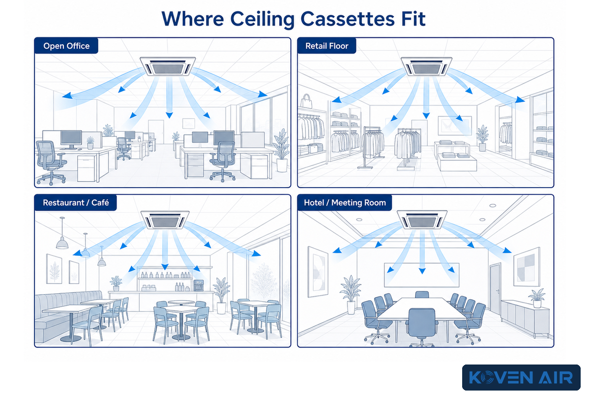
Cassette systems earn their keep in mid-size commercial rooms with an accessible ceiling void and either an existing hydronic riser or straightforward refrigerant line routing. Open-plan offices, retail floors, restaurants, classrooms, and small hotel function rooms recur in published cassette application guidance.
Hydronic FCU cassettes specifically suit projects that already run, or plan to run, a central plant, including hospitals, hotels and high-rise office buildings. Each application shares the same underlying requirement of an existing or planned chilled-water/hot-water loop. DX/VRF cassettes show up more often in standalone buildings and phased, tenant-by-tenant retrofits where a central plant was never part of the design.
In a space-tight retrofit, a cassette may fit only where the ceiling void has enough depth. Smaller or obstructed rooms can use a different terminal type instead of forcing a full-cassette solution into every zone.
When a Cassette System Is the Wrong Choice
Cassette AC is the wrong call in a few recurring situations. Any ceiling void that can’t fit the selected cabinet, hangers, piping, drain route and service envelope rules the format out before a technology decision is made for that room.
Very small enclosed rooms may not justify a dedicated cassette head when a compact wall-mounted or ceiling-suspended unit is easier to install and service. Spaces with no outdoor-air path and no room budgeted for a DOAS are another poor fit: the cassette can cool correctly while indoor-air complaints persist because ventilation was never solved. Any room where condensate can’t be given a working gravity fall or pump lift is also a drainage failure waiting to happen, regardless of how carefully capacity was selected.
Cost, Maintenance, and Lifespan: What to Expect
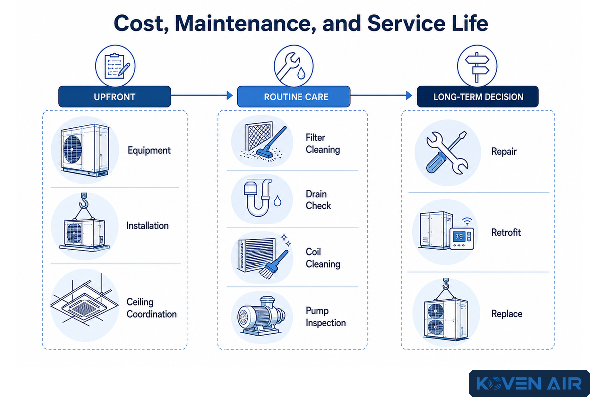
Commercial cassette AC installation usually costs more upfront than an equivalent wall-mounted mini-split of the same capacity, largely because of ceiling-access labor and, for DX/VRF, refrigerant piping. A hydronic FCU cassette’s cost only makes sense when the shared central plant is included in the project comparison. Pricing the cassette as a standalone system ignores the capital and energy work performed by the chiller or boiler.
O&M basedservice life depends on duty, environment and maintenance history
Inspect routinelyset filter and drain intervals from the manufacturer’s O&M schedule and site conditions
Load firstcapacity and airflow must follow the room heat-load calculation
Routine maintenance differs by technology path more than by cassette type: DX/VRF service centers on refrigerant-circuit checks and outdoor-condenser cleaning, while hydronic FCU maintenance is mostly about plant-side water quality and strainer/valve inspection, since the indoor coil itself has no refrigerant to leak. Both paths share filter, coil and condensate-pan inspections. The correct interval comes from the manufacturer’s O&M schedule, then tightens when dust load, occupancy, operating hours or drain history justify it. That approach follows CIBSE maintenance guidance, which starts with asset-specific manufacturer or installer instructions and adjusts maintenance effort for building function, operating hours, environment, equipment condition and installation standard. A NIST study of underperforming HVAC equipment reinforces why installation and maintenance conditions matter even when the unit selection is sound. No single service-life number applies to every cassette system: duty cycle, water or refrigerant quality, corrosion exposure, controls, parts availability and maintenance records all influence replacement timing.
2026 Market Outlook: Why Demand for Cassette Systems Is Shifting
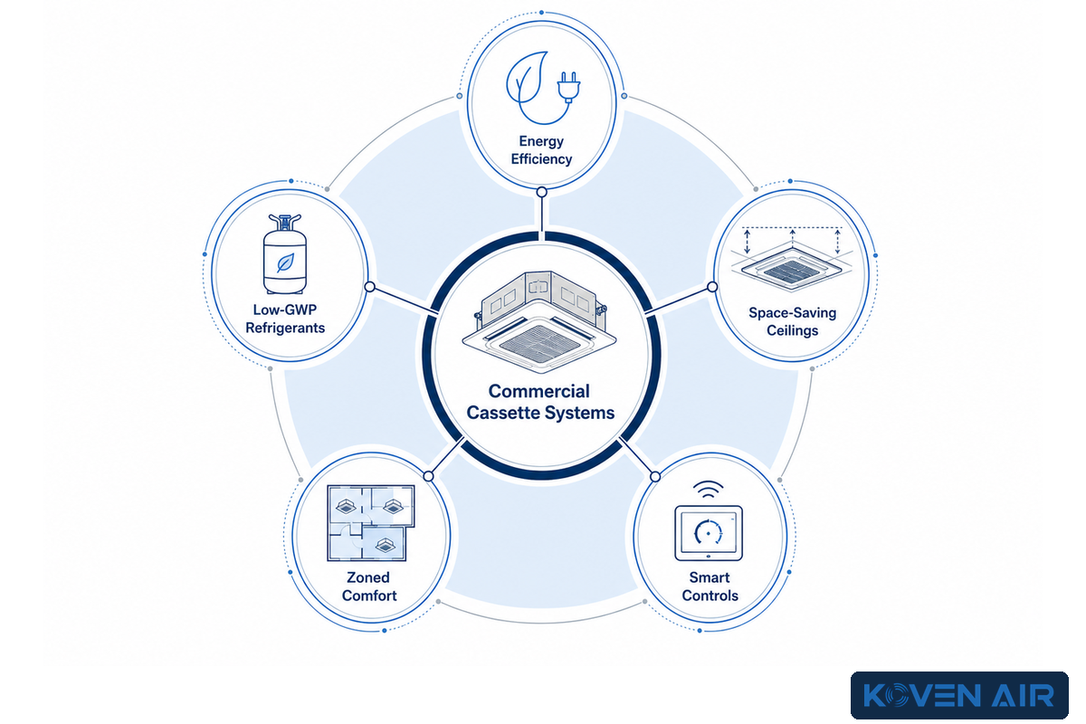
For US commercial cassette buyers, the most consequential near-term driver isn’t market growth at all. It’s the EPA’s staged HFC transition, which treats refrigerant GWP, system sector, component manufacturing/import date, installation date and qualifying permit status as separate compliance questions. Reducing that schedule to a one-line “2027 deadline” is too broad for procurement.
Refrigerant Compliance Deadlines Are Reshaping the DX/VRF Replacement Cycle
The EPA’s current sector guidance says certain new VRF systems using refrigerant above 700 GWP may be installed until January 1, 2027 when all components were manufactured or imported before January 1, 2026. For a system detailed in a building permit approved before October 5, 2023, that installation window can extend to January 1, 2028 under the stated conditions. Because the underlying eCFR restriction also contains sector-specific effective dates, a project team should confirm the system category and component history rather than applying one date to every commercial VRF installation.
Technically, both technology paths keep moving toward finer-grained modulation: inverter compressors are close to standard on new DX/VRF cassette lines for the part-load efficiency and humidity-control gains discussed earlier, and the hydronic side is seeing more variable-speed pump and plant controls doing the equivalent job for water flow rather than refrigerant flow.
Choosing Between DX/VRF and Hydronic Cassette Systems
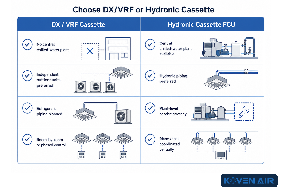
The practical decision between DX/VRF and hydronic cassette systems usually comes down to one question before any spec sheet gets compared: does the building already have, or firmly plan to have, a central chilled-water/hot-water plant? Everything else in the comparison above is secondary to that one fact.
6-Point DX-vs-Hydronic Cassette Fit Score
- Central plant present or firmly planned favors hydronic FCU; without one, hydronic isn’t viable at any price.
- Refrigerant permitting / ASHRAE 15 zone constraints favors hydronic wherever small occupied rooms push against a refrigerant concentration limit.
- Simultaneous heating and cooling need favors a 4-pipe hydronic layout or a model-specific heat-recovery VRF design with the required branch hardware and controls.
- Phased, tenant-by-tenant fit-out timeline favors DX/VRF, which scales zone-by-zone without central-plant coordination.
- GWP/refrigerant-compliance timeline sensitivity favors hydronic at the room terminal, which carries water rather than refrigerant and doesn’t depend on a VRF condensing unit’s EPA transition status.
- On-site plant maintenance capability favors DX/VRF where no plant operator is on staff to run a chiller/boiler system.
If your building already seems like a potential fit, then you’ll want to review Koven Air’s hydronic cassette fan coil unit specifications in tandem with a chiller-sizing discussion, as these two components can’t practically be addressed in isolation.
Key takeaway
If a central chilled- or hot-water plant already exists — or is already budgeted — a hydronic cassette FCU is usually the more defensible long-term choice; for a phased, tenant-by-tenant retrofit with no plant in sight, DX/VRF remains the more buildable path today.
Frequently Asked Questions
Are cassette air conditioners any good?
Yes, commercial cassette air conditioners are a well-established, reliable format when sized correctly and installed with proper condensate drainage; most complaints trace back to installation shortcuts, not the format itself.
Both DX/VRF and hydronic FCU cassette technologies have been in commercial use for decades. When cassette units under-deliver, common checks include sizing, ceiling clearance, airflow and condensate routing. Following the manufacturer’s filter, coil and drain-inspection schedule helps prevent avoidable service calls. Before handover, confirm structural support, drain testing, service clearance and filter access. During operation, compare comfort complaints against the unit’s published airflow, controller settings and the room load instead of assuming the ceiling format itself is defective. A repeat leak or airflow problem calls for a documented root-cause check, not another rule-of-thumb adjustment.
What are the disadvantages of cassette AC?
The main disadvantages are a model-specific ceiling-void requirement, harder service access than a wall-mounted unit, and dependence on a separate ventilation system, since cassettes don’t bring in outside air on their own.
Directional throw can also leave dead zones behind partitions or tall furniture, and hydronic cassette FCUs add a dependency on the building’s central plant capacity. Installation needs real structural support above the suspended grid. Open rooms usually suit the airflow pattern, but partitions can interrupt horizontal throw and may force a multi-unit layout.
Is an inverter or non-inverter cassette AC better for commercial use?
Inverter (variable-speed) cassette units are generally the better fit for most commercial spaces because they modulate capacity to match partial loads, giving steadier temperature and humidity control with less on/off cycling noise than a fixed-speed non-inverter unit.
Non-inverter units may cost less upfront and can remain a reasonable choice for spaces with fairly constant, predictable loads. For occupied commercial floors with variable occupancy and equipment loads, compare published part-load performance, controls and expected operating hours instead of assuming one technology has the better lifecycle cost in every project.
What is the lifespan of a cassette AC?
There is no universal cassette-AC lifespan; replacement timing depends on operating hours, environment, water or refrigerant quality, maintenance history, controls and parts support rather than one fixed number.
A unit that receives scheduled filter, coil, drain, valve and refrigerant-circuit service can remain useful far longer than one operating with blocked airflow or recurring condensate faults. For budgeting, review the manufacturer’s service guidance, the installation’s failure history and whether major components remain available instead of applying one generic year range.
Can a cassette AC cool a large room?
A cassette can cool a large room only when its published capacity, airflow and throw pattern match the calculated load and geometry; large or partitioned rooms often need multiple coordinated units.
To expand coverage, designers can coordinate several cassette heads through a DX/VRF multi-zone controller or a common hydronic loop instead of pushing one unit beyond its published airflow and throw. An oversized unit can short-cycle and weaken humidity control, so the final layout should follow the room-by-room load and occupied-zone airflow review.
Specifying a Chilled-Water Cassette FCU for Your Project?
Koven Air manufactures hydronic cassette fan coil units for commercial projects that already have, or firmly plan to install, a central chilled- or hot-water plant and need a model-by-model submittal review before procurement. Include the room loads, water temperatures and airflow requirements in your inquiry.
Why We Wrote This Guide
Search results for “commercial cassette air conditioner” return mostly product pages and little direct technology comparison. Many buyers researching this term don’t yet know that DX/VRF and hydronic FCU are two different systems sharing one name. We wrote this guide to lay out that distinction plainly, alongside the ceiling-clearance, sizing and refrigerant-compliance details a specifier needs, while showing where Koven Air’s hydronic FCU line fits and where it doesn’t.
References & Sources
- Central Air Conditioners Test Procedure Final Rule U.S. Department of Energy
- Underperforming Energy-Efficiency HVAC Equipment Study National Institute of Standards and Technology
- Maintenance of Workplace Equipment, Devices and Systems Chartered Institution of Building Services Engineers
- Technology Transitions: HFC Restrictions by Sector U.S. Environmental Protection Agency
- Minimum HVAC Equipment Performance Ratings (AHRI 210/240) up.codes
- SEER2 HVAC Efficiency Standards ServiceNation
- VRF, DOAS, and High-Performance Buildings HPAC Engineering
- US Patent 6,481,237 B2, Cassette-Type Air Conditioner Deflector Design Google Patents
- US Patent 6,470,699 B1, Ceiling Cassette Air Conditioner Housing Design Google Patents
Related Resources
- Koven Air Chilled-Water Cassette Fan Coil Units full specifications for the hydronic FCU product line covered in this guide.
- Koven Air HVACR Product Range chillers, heat pumps, and desiccant dehumidification equipment alongside the cassette FCU line.
![Horizontal Fan Coil Unit Project Guide [Step-by-Step]](https://kovenair.com/wp-content/uploads/2026/09/horizontal-fan-coil-unit-guide-featured-1-768x512.png)


![Commercial Rooftop Unit Guide: Types, Sizing & Costs [2026]](https://kovenair.com/wp-content/uploads/2026/07/commercial-rooftop-unit-guide-featured-2-150x150.png)