Get in Touch with Koven Air Company

Updated October 2026
Quick Specs
- Application: recirculating, tower-based commercial and industrial chiller plants.
- Supply measurement: water entering the chiller condenser.
- Temperature limit: the installed model’s approved operating envelope.
- Energy comparison: chiller, tower fans and affected pumps at comparable conditions.
Condenser water supply is the water entering a water-cooled condenser to absorb rejected heat. In a tower-based plant, it comes from the cooling tower and goes back, warmer. Its useful temperature depends on tower capacity, chiller limits and total plant power. Lower numbers alone don’t prove better performance.
Condenser water supply must stay within the approved limits of the chiller and the operating range of the tower. Choose the operating point by comparing the total plant power under equivalent conditions.
Key points
- The coldest tower water can require more combined chiller-and-fan power.
- Startup limits and continuous-running limits can refer to different measurement points.
- Wet-bulb temperature constrains evaporative cooling; a design approach isn’t an all-weather promise.
- Winter protection and the site’s water-management program remain operating conditions.
Condenser water supply vs chilled water: follow the heat
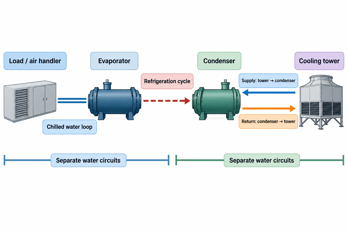
The chilled water loop receives heat from the process load, while the condenser water loop dumps process heat to the surroundings. They exchange energy through the refrigeration cycle within the chiller, and don’t become part of the same water circuit. The U.S. Department of Energy’s cooling-system overview shows this separation, which can be useful when a drawing labels several pipes simply “supply.”
What is condenser water supply and return?
Condenser water supply flows to a water-cooled condenser; return water leaves it after absorbing the heat rejected by the refrigerant. In the recirculating arrangement discussed here, warm condenser water flows to a cooling tower. The supply and return labels describe flow with respect to the condenser, and not to the coldest and hottest pipes in the facility.
On the load side, water is pumped through an air handler coil (or process heat exchanger). In HVAC systems, the coil removes building heat from return air. The heated water is returned to the evaporator where refrigerant absorbs the heat. The compressor raises the pressure of the resulting vapor before it reaches the condenser.
Heat transfer on the condenser side allows gaseous refrigerant to condense into liquid refrigerant. The condenser must reject both the evaporator load and the compressor’s contribution. Cooled water from the tower takes up that heat and circulates back outside. Evaporation at the tower provides the transfer of heat to ambient air.
This working principle shows how the chilled water system can retain its supply target whilst the condenser circuit still wastes energy. Trace both loops separately before you try to adjust either one. The evaporator chiller guide provides more details on load side heat exchange.
Set a condenser water temperature envelope
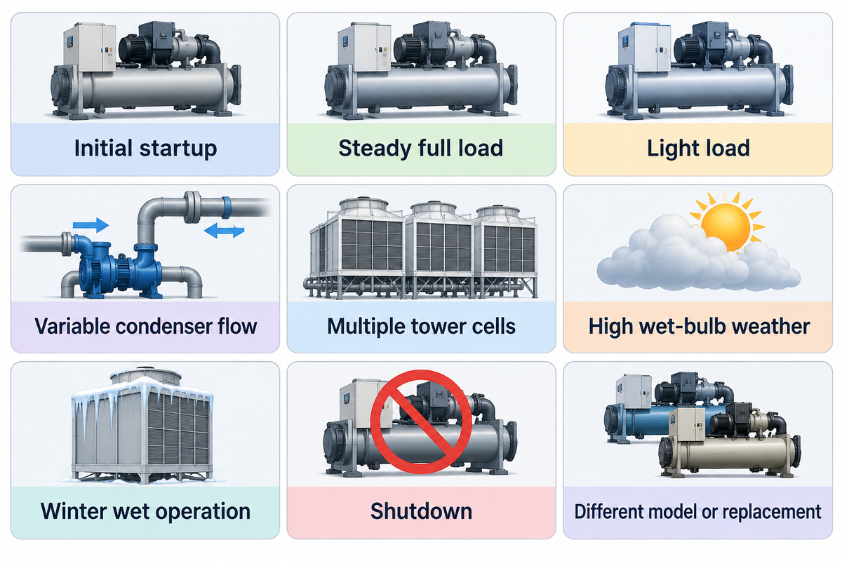
An acceptable operating envelope identifies permissible temperatures and specifies measurement locations and conditions for the installed chiller. A familiar design temperature isn’t a universal minimum. Start up, continuous operation, water flow and refrigerant-pressure limits are to be specified in the controls specification for a water cooled chiller.
One concrete example is the operating range table from the Carrier 30DW catalog. It states a minimum condenser entering water temperature of 13°C at start up and a minimum leaving water temperature of 19°C during operation. These are different measurement points. The catalog also requires an optional two- or three-way water flow control valve at the condenser when its leaving water temperature is below 19°C. They don’t express a 13-19°C entering water band and don’t set specs for another manufacturer’s commercial chiller.
For a controls retrofit, controller documentation and the approved submittal take precedence over a temperature copied from another plant. Lift, the refrigerant-pressure difference the compressor works against, also changes with load and evaporator conditions. An acceptable water reading doesn’t cancel the protection against flow and pressure.
| Condition | Information needed | Controls consequence |
|---|---|---|
| Initial startup | Entering-water limit and startup sequence | Use startup permissives before normal reset |
| Steady full load | Approved temperature and flow selection | Keep the operating point within that selection |
| Light load | Minimum lift and stable-load limits | Retain pressure and capacity protections |
| Variable condenser flow | Minimum flow and allowable rate of change | Coordinate pump and chiller controls |
| Multiple tower cells | Minimum distribution flow per active cell | Stage cells without starving the fill |
| High wet-bulb weather | Tower performance at actual duty | Recognize an unattainable temperature request |
| Winter wet operation | Tower-specific temperature and icing limits | Apply the approved winter sequence |
| Shutdown | Basin, piping and restart requirements | Protect standing water and maintain water management |
| Different model or replacement | New submittal and controller limits | Reassess inherited settings before reuse |
Take for instance an inherited plant where the operator wishes to lower a fixed setpoint after a mild-weather visit. The first important records to analyze would be the machine model, controller revision, and alarm history, in addition to the locations of the inlet and outlet sensors. A low-temperature trip after a reset doesn’t confirm which protection acted. If the contractor gives only a target temperature, procurement still doesn’t have the conditions under which the machine can reach and sustain that temperature. The proposal should include a machine-specific sequence and an acceptance test, with responsibility for the tower and pump interfaces defined. That prevents a cheap controls change from becoming an unresolved dispute between equipment suppliers.
Cooling tower approach: a feasible wet-bulb target
Tower approach is the difference between the water temperature leaving the tower and the wet-bulb temperature of the air entering the tower. ASHRAE’s terminology defines these measurement points explicitly. Tower approach is determined by the tower and the conditions under which it operates; therefore, assuming a fixed design approach applies in every operating condition may give a false impression of system performance.
3-Limit Condenser Setpoint Window
The 3-Limit Condenser Setpoint Window compares the tower’s achievable outlet temperature to the approved chiller lower and upper bounds.
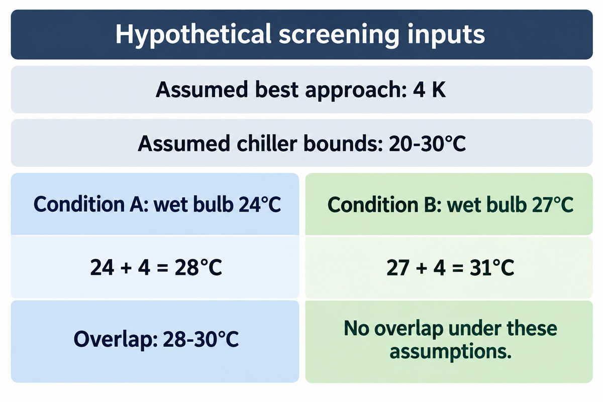
Example: assume the best achievable tower approach is 4 K at a stated load, water flow and allowed fan operation. Also assume the relevant chiller entering-water limits are 20°C and 30°C. These inputs describe a screening exercise; operating limits for a real machine must come from its own selection.
| Input or result | Condition A | Condition B |
|---|---|---|
| Tower-inlet wet bulb | 24°C | 27°C |
| Assumed best achievable approach | 4 K | 4 K |
| Lowest achievable outlet | 24 + 4 = 28°C | 27 + 4 = 31°C |
| Assumed chiller lower bound | 20°C | 20°C |
| Assumed chiller upper bound | 30°C | 30°C |
| Temperature overlap | 28–30°C | None under these assumptions |
Condition B doesn’t become feasible by clamping a controller request to 30°C: the assumed tower capability still bottoms out at 31°C. The useful decision is to revisit the load, operating configuration or equipment selection. If the 4 K input is merely a design point, rather than the best achievable approach at that duty, the table flags a question; it doesn’t prove the existing tower can’t perform better. Use the relevant performance curve or a properly controlled test to settle that question. Even in Condition A, a numerical overlap says nothing by itself about minimum flow, stable lift or safe winter operation.
How do you find chiller approach?
Chiller approach compares refrigerant saturation temperature with water temperature at the relevant heat exchanger. On the condenser, use the measurement locations specified by the manufacturer. This is different from cooling tower approach, which uses entering-air wet bulb. A high value at one component can’t identify a fault at the other without matched operating data.
For tower evaluation, a remote weather-station reading may not represent air at the tower inlet. Sensor location belongs in the test record, along with calibration. The National Laboratory of the Rockies’ tower guidance, connects performance with design conditions, operation and commissioning rather than one isolated temperature.
Fixed setpoint or reset: compare total plant power
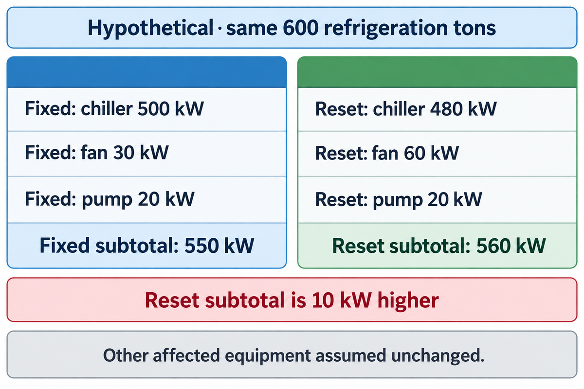
A reset strategy earns its place when it reduces the affected plant’s power level while satisfying the load and limits. Cooler condenser water can reduce compressor input. However, tower fans require more input. Analyzing chiller’s power level alone doesn’t take the exchange into account; analyzing unmatched operating periods can lead to misleading results, even if all the meters are correct.
“the lowest possible leaving tower water temperature does not always conserve system energy.”
Mick Schwedler, Trane, Chiller/Tower Interaction
Schwedler’s analysis compares chiller and tower interaction under stated modeling assumptions. It justifies the trade-off, and doesn’t indicate a universal saving per degree. Later, in condenser-water control discussion, Trane also mentions the static lift of an open system complicates estimation of pump-power. Use the actual duty and measured input of the water pump instead of applying a cubic speed rule to the entire open circuit.
4-Point Reset Acceptance Record
In considering a reset strategy, the 4-Point Reset Acceptance Record takes into account weather, cooling duty, summed equipment power and operating stability.
| Recorded item | Fixed strategy | Colder reset |
|---|---|---|
| Illustrative cooling duty | 600 refrigeration tons | 600 refrigeration tons |
| Chiller input | 500 kW | 480 kW |
| Tower fan input | 30 kW | 60 kW |
| Condenser pump input | 20 kW | 20 kW |
| Compared power subtotal | 550 kW | 560 kW |
| Subtotal per unit cooling duty | 0.917 kW/ton | 0.933 kW/ton |
| Other affected equipment | Assumed unchanged; include it if the test changes its input | |
The chiller saves 20 kW, but the fans add 30 kW, leaving a 10 kW higher subtotal. For a plant manager, that reverses a compressor-only recommendation. For finance, it’s still only arithmetic: a real 10 kW difference must exceed the uncertainty of the measurement and comparison method. Representative tower-inlet wet bulb, cooling duty, leaving chilled-water temperature and equipment staging need to match or be accounted for. Stable repeated periods are more useful than a screenshot during a transition. A one-period comparison can’t establish annual energy savings, especially when seasonal loads and air temperature change the equipment combination.
The Department of Energy’s approach requires the inclusion of all relevant parameters. To prevent omitted pumps/auxiliaries from turning apparent benefits into accounting errors, agreement on the measurement boundary must be prior to the test.
Diagnose warm supply before buying a larger tower
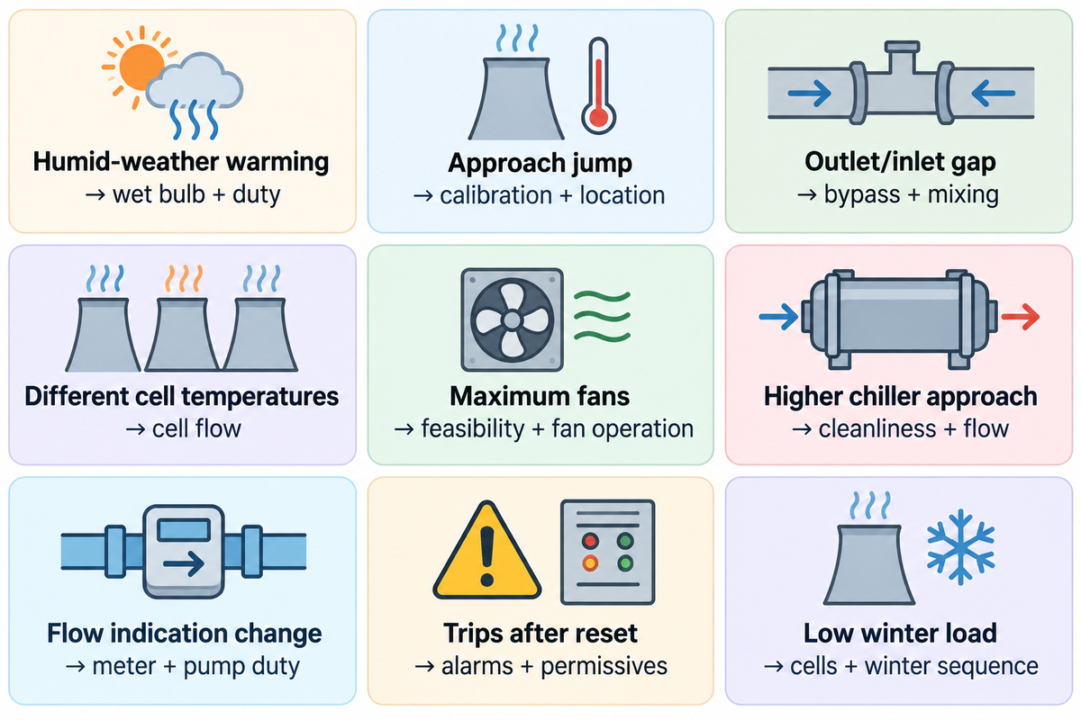
Warm supply is a symptom with many possible causes. Changes in weather, poor water distribution, and incorrectly located sensors may all be causes. Compare the readings for the towers, chiller and piping on the same time base prior to attributing inefficiency to insufficient tower capacity.
Temperature sensors should be addressed as early as possible. The discussion of tower measurements in Vaisala’s report describes issues with humidity measurements and control of evaporative coolers. Using an instrument that’s accurately calibrated doesn’t solve the problem of placing the instrument in an unrepresentative air stream.
| Observation | Check before changing capacity | Decision supported |
|---|---|---|
| Supply warms with humid weather | Tower-inlet wet bulb and rated duty | Separate weather limitation from degradation |
| Reported approach rises suddenly | Sensor calibration and measurement locations | Correct a measurement fault before retuning |
| Tower outlet is cooler than chiller inlet | Bypass position and mixing arrangement | Resolve the piping/control path |
| Cells show different outlet temperatures | Distribution and water flow in each active cell | Correct uneven loading before adding cells |
| Fans remain at maximum | Setpoint feasibility and fan operation | Stop treating an impossible request as a capacity test |
| Chiller approach increases | Condenser cleanliness and approved flow | Investigate heat transfer on the condenser side |
| Flow indication changes unexpectedly | Meter calibration and pump duty | Validate the input before diagnosing capacity loss |
| Trips follow a reset | Alarm history, lift and flow permissives | Identify the protection that acted |
| Winter load falls below expectations | Heat load, active cells and approved winter sequence | Address cold-weather exposure before energy tuning |
This is a diagnostic ordering tool, not a list of confirmed causes. The laboratory’s operating and maintenance guidance supports evaluating equipment condition and operating context together. Cleaning and treatment work also belongs in the comparison baseline; a dirty baseline and clean trial don’t isolate a control change. Use the water-cooled chiller maintenance guide to develop the maintenance side of that record.
Cold-weather operation and chiller protection
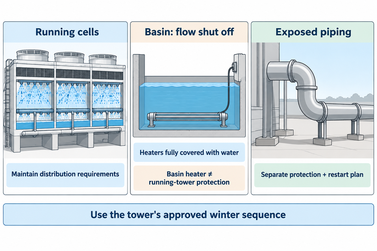
Cold-weather condenser water systems need provisions for running equipment and standing water after shutdown. Minimum conditions of Chiller protection are provided for the machine. Icing exposure is dependent on tower flow distribution, heat load and local temperatures. A mixed supply temperature can’t establish that all tower cells are operating safely.
In the March 2014 article Cold Weather Operation of Cooling Towers, SPX Marley engineer Paul Lindahl discusses open-circuit towers that serve chillers and economizers. This historic guidance differentiates between protection for loaded operation and shutdown; use the current instructions for the tower in question for its actual operation. Basin heaters are for the basin with the system flow shut off and the heaters fully covered with water; exposed piping is to be accounted for separately. Basin heaters shall not substitute for protection of a running tower’s water distribution.
Let’s say production heat in a facility is less this winter than originally designed. A common header can be relatively warm while one or more cells develop lower temperature regions. Setting a minimum limit on the building controller doesn’t guarantee flow through each cell or protect stagnant piping. The practical solution is to match a winter sequence to the tower including staging of each cell, minimum distribution flow, shut down provisions, and restart needs. The operator must also define a response to local icing. Closed-circuit fluid cooling requires its own instructions, and this open-circuit example doesn’t transfer automatically.
Do
- Use the tower’s approved winter sequence.
- Keep each operating cell within its distribution requirements.
- Include exposed piping and restart in shutdown planning.
Don’t
- Assume a warm mixed header proves every cell is safe.
- Reduce flow solely to create a larger temperature range.
- Treat a basin heater as protection for all circulating water.
Water management is part of the operating envelope. CDC guidance on cooling towers, identifies temperature, biofilm, water age and disinfectant residual as factors relevant to Legionella control. The spray water side of a closed circuit tower also may present a risk. Energy management and seasonal shutdown must maintain the site’s water management program; a favorable electricity reading isn’t a health control.
Specify the retrofit and prove the result
A statement of work describes what a contractor will measure, the equipment which reset can control, and how acceptance will be determined. Procurement needs a defined scope, operations needs stable cooling, and finance needs a comparison which includes all affected energy use. These descriptions must be included in the same request.
Use the fields below with the site’s approved values to fill out the quotation request and turn it into a test record using the 4-Point Reset Acceptance Record. The DOE measurement framework provides support for this by focusing on relevant measured parameters. The worksheet is an editorial synthesis, not a published commissioning standard.
RFQ checklist: define the test before buying the reset
| Parameter | Recommended range | Why it matters | How to verify |
|---|---|---|---|
| Chiller temperature envelope | Model-approved °C limits, with inlet/outlet labels | Prevents a mismatched setpoint | Approved selection and controller documents |
| Condenser and cell flow | Approved L/s range for each operating configuration | Protects machine flow and tower distribution | Meter records and equipment flow requirements |
| Weather and cooling duty | Agreed wet-bulb °C and cooling kW comparison bands | Separates operating changes from reset effects | Common-time-base trend data |
| Electrical boundary | All affected equipment, measured in kW and kWh | Captures fan and pump tradeoffs | Meter schedule and summed records |
| Measurement quality | Project-agreed °C, flow and kW uncertainty limits | Prevents noise being called a saving | Calibration records and uncertainty review |
| Stability and seasonal duty | Agreed load bands and representative test periods | Exposes cycling, trips and seasonal limitations | Alarm history and repeated stable comparisons |
The acceptance decision should determine whether cooling requirements were satisfied, protections were maintained, and the power difference observed was meaningful. If weather drift or sensor uncertainty obscures the difference, then the result is inconclusive. It’s neither a saving nor a failure. A second representative test is more useful than adjusting the accounting boundary after seeing the numbers.
When replacing equipment, be sure to include the existing tower selection and available flow. The Koven Air industrial chiller selection is the product starting point; a condenser-water target becomes a selection input only when its operating conditions are attached.
What is changing in condenser water controls
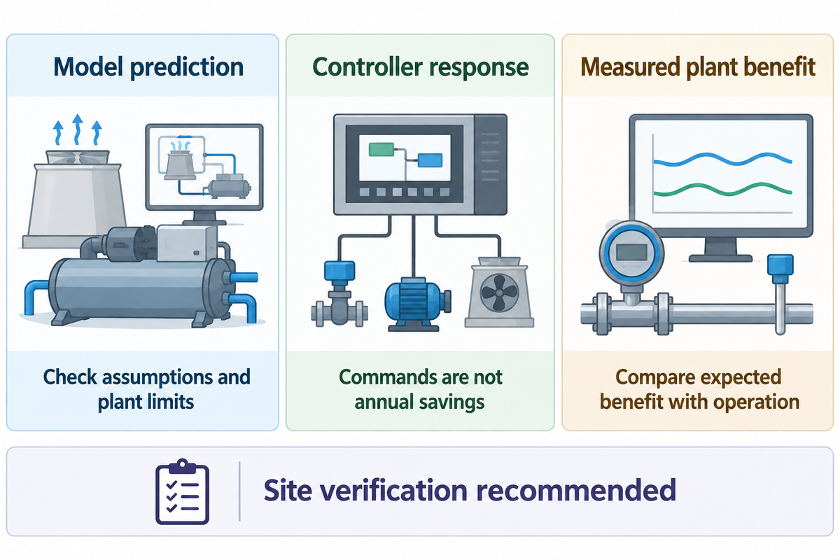
Recent studies have shown how certain models can coordinate the behavior of chillers in conjunction with pumps and fans. The most useful distinction for buyers remains between a model which shows promise, a controller which implements commands and a plant which has demonstrated savings in service. Each responds to a different purchasing question.
Xiao Chen and colleagues in an October 2025 Buildings paper examine direct control of condenser pumps and tower fans. Their simulated plant shows a savings of 13.2% at a 20% part load compared to constant speed operation of fans and pumps. A different physical experiment tests frequency response. The saved percentage from the simulation isn’t a measurement of hotel retrofit savings. Several of the authors are employees of an energy services company, Guangzhou Shijie Energy-Saving Technology Co., Ltd., as disclosed in the paper.
A May 2025 preprint by Gulai Shen, Gurpreet Singh and Ali Mehmani of Nantum AI employs combined use of calibrated simulation and synthetic data to arrive at optimal tower fan operation and condenser water temperature. The model behind the potential savings shown in the paper needs to be checked against the constraints, loads and meters of the plant, prior to the model taking control of equipment.
Older control concepts exist. WO2008079829A9, published in 2008 describes control of a condenser-water temperature and flow setpoint. The inventor is Scot M. Duncan. The patent describes a historical control strategy, not a Koven Air invention. This patent, however, doesn’t address the legality of current products.
The 2025 edition of ASHRAE Standard 90.1 contains 105 addenda and updates the minimum efficiency requirements for cooling towers and other equipment. The publication year of the edition doesn’t determine which edition a project jurisdiction has adopted.
An auditable control sequence is the sensible deliverable for a retrofit specified today. It is a control sequence with fallback behavior and meter access, with an agreed verification method. The ownership should have the opportunity to verify the expected benefit using the requested method. An optimizer should communicate which loads and what weather conditions were considered in the model. This way, the owner can compare the expected benefit to actual operation to determine if the proposed controls retrofit makes economic sense.
Frequently Asked Questions
Is it true that only water-cooled chillers have condenser water?
Water-cooled condensers use a water circuit; an air-cooled chiller rejects condenser heat directly to air.
A conventional air-cooled condenser uses refrigerant coils and fans, so it doesn’t need the tower-to-condenser loop described here. Water-cooled chiller systems can use different heat-rejection arrangements, and other refrigeration equipment can also have water-cooled condensers. Identify the equipment and piping topology before applying a tower-based sequence. The term “condenser water” describes the circuit’s function, not an exclusive class of building or cooling load.
Do condenser water supply lines need to be insulated?
Insulation depends on the pipe’s temperature, surroundings and project requirements.
A pipe operating below the surrounding air’s dew point can collect condensation, while outdoor piping also raises weather and freeze-protection questions. Those are different design problems. Insulation alone doesn’t keep stagnant water from freezing indefinitely, and a conventional heating and cooling specification may not cover every exposed condenser branch. The piping designer should define insulation, vapor control where needed, weather protection and any separate freeze-protection provision. The choice also affects access for maintenance and inspection. It can’t be settled solely by calling the line condenser water rather than chilled water.
Why is condenser water warmer than chilled water?
The two circuits operate at different points in the refrigeration cycle and perform different jobs.
The chilled water loop collects heat from the process or building and gives it to refrigerant in the evaporator. The compressor then raises the refrigerant’s pressure and temperature so the condenser can transfer that energy to another medium. Condenser water receives the rejected heat and carries it toward the cooling tower. Its temperature therefore reflects the heat-rejection conditions, while chilled water temperature reflects the cooling service required by the load. The condenser also rejects the compressor’s contribution. These circuits aren’t normally mixed to obtain an average supply temperature. Comparing their readings is useful only when the measurement points and operating duty are known. A warmer condenser return can be entirely consistent with normal heat rejection rather than evidence that the load-side chilled water system has failed.
Why does an open condenser water system consume makeup water?
Evaporation removes heat but also removes water, and blowdown removes concentrated dissolved solids.
Makeup replaces these losses and any drift or leakage. It’s separate from the recirculating supply flow. A sudden makeup increase should be investigated against heat load, blowdown settings and leaks, rather than assumed to mean the circulating pump needs more capacity.
What are the disadvantages of cooling towers?
Cooling towers require water management, maintenance and weather-dependent operation.
Water consumption, treatment, fan and pump electricity, icing exposure and aerosol control all affect the installation. Compare these obligations with the cooling duty and available heat-rejection alternatives.
Key takeaway
Select condenser water supply temperature inside a verified operating envelope, then judge the reset using all affected plant power at comparable conditions.
Geared toward the load profile you operate under, your tower duty and approved operating limits, the industrial chillers selection guide allows a broader selection of equipment.
Technical basis: public engineering guidance and named manufacturer documents reviewed in October 2026. The assumed examples illustrate decisions and don’t report Koven Air plant tests, guaranteed savings or a commissioned control sequence.
References & Sources
- DOE: cooling water efficiency opportunities
- ASHRAE: cooling terminology
- National Laboratory of the Rockies: cooling towers
- DOE: measurement and verification options
- ASHRAE Journal: Cold Weather Operation of Cooling Towers
- CDC: controlling Legionella in cooling towers
- Buildings: direct optimal control of cooling water systems
- arXiv: co-optimizing condenser-water temperature and tower fans
- ASHRAE: Standard 90.1, 2025 edition