Get in Touch with Koven Air Company


A valve can fit the pipe and still be wrong for the coil. Valve authority explains how much of a hydronic circuit’s pressure drop belongs to its control valve. That determination influences how valve movements affect the water flow, especially if only a small portion of a circuit’s design cooling duty is required to serve a space.
For a buyer, the useful question is whether a proposed valve can control the selected coil under the given pressure conditions. This guide compares three Kvs values using explicit assumptions, separates PICV operating limits from shutoff requirements, and gives the mechanical designer, purchasing team and commissioning contractor a shared request for quotation.
Valve authority and installed flow control

Valve authority is the fraction of design pressure drop of a defined circuit that’s consumed by the fully open control valve. A valve that loses 20 kPa in a circuit losing 40 kPa has an authority of 0.50. The ratio can be used to describe installed flow control, but it doesn’t provide any assurances on temperature stability.
What does “valve authority” mean?
Authority is the valve’s hydraulic influence on a defined circuit. It can be calculated using the pressure drop across the fully open valve and the total circuit loss at the design flow. Low valve authority means other circuit components consume a larger share of the available pressure, so the installed response can differ substantially from the inherent valve characteristic.
An inherent characteristic describes flow coefficient versus travel under a constant pressure difference. Pressure across the control valve changes with movement and other branches opening or closing. An equal-percentage valve, a linear globe valve and a characterized ball valve, however, need their installed conditions considered. The actuator’s indicated opening isn’t a direct reading of delivered cooling.
“Designers must consider multiple factors when selecting a valve for an application”
The NIH design note connects valve selection with coil behavior and control-loop tuning. For a wider introduction to terminal equipment, the fan coil units guide explains the equipment choices that precede valve selection.
At a stated design flow, a 20 kPa valve loss and 20 kPa remainder give 50% authority. A quotation that supplies only a connection size leaves that calculation unresolved. Ask for the coefficient and pressure boundary before accepting a proposed substitute, even when its threaded connections match.
Calculate authority at one defined design flow
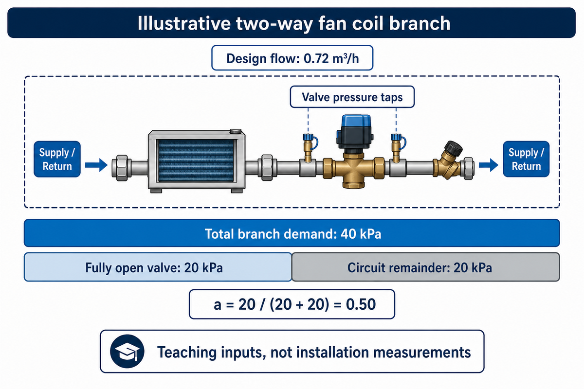
The authority is calculated by dividing the fully open valve pressure drop by the sum of that loss and the remaining losses of the controlled circuit. All these values must relate to the same flow and circuit boundary. Combining a coil’s 20 kPa design loss with a pump’s unrelated maximum head is inaccurate.
How do I calculate the valve authority?
Use a = ΔPv / (ΔPv + ΔPrest), where ΔPv is the fully open valve loss and ΔPrest is the loss through the rest of the defined circuit at the same design flow. Include the relevant coil, pipe and fittings and the balancing device once each. Use consistent pressure units and record the locations that define the circuit.
Consider an illustrative two-way fan coil branch carrying 0.72 m³/h of water. Its selected valve loses 20 kPa; the coil and remaining branch components together lose another 20 kPa. The calculation is a = 20 / (20 + 20) = 0.50. Total branch demand is 40 kPa. These are teaching inputs, not measurements from a Koven installation.
In the drawing show the supply and return branch connections and show the taps used to measure pressure drop across the valve. If a balancing valve is included in the 20 kPa remainder, don’t include its loss again. Nor should elevation be included as additional friction loss in this example of a closed circuit.
A designer reviewing a replacement quote should return a calculation with a different boundary for correction before comparing prices. The valve authority calculator can verify the calculation once the numbers are agreed. Use it for the ratio calculation; confirm PICV operating limits and actuator close-off requirements separately.
For the 0.72 m³/h example, both the 20 kPa valve loss and the 20 kPa circuit remainder belong to the same operating point. Record the condition along with the result. A pressure reading taken after another branch closes is valuable commissioning evidence, but it cannot silently replace a design input.
Compare three Kvs sizes before buying a valve
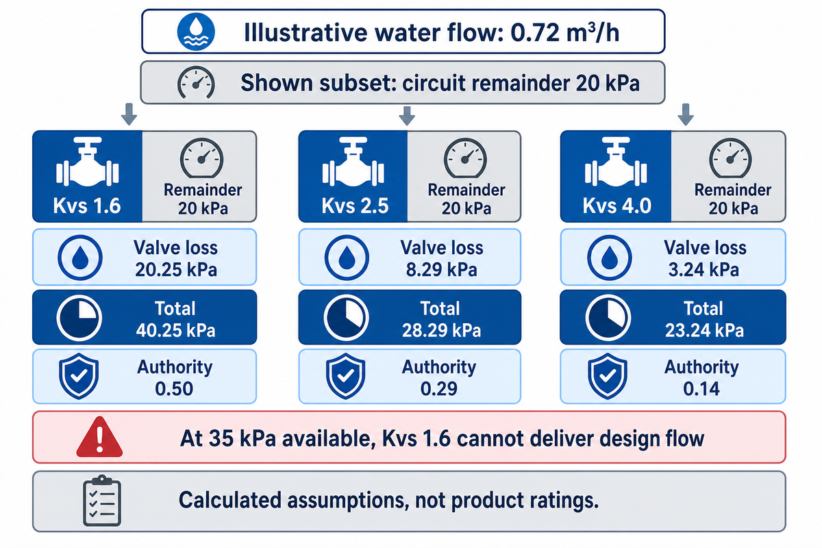
With an illustrative water flow of 0.72 m³/h, ideal valve losses of 20.25, 8.29 and 3.24 kPa, respectively, were obtained at Kvs values of 1.6, 2.5 and 4.0. The higher the coefficient, the lower the loss. The reduction in loss may or may not mean an improvement in selection, depending on the loss in the remaining circuit, available pressure and the installed response needed.
What is KV vs CV?
Kv is a metric flow coefficient based on cubic metres per hour of water at a 1 bar pressure difference. US Cv uses gallons per minute at 1 psi under its reference conditions. They aren’t interchangeable; Cv is approximately 1.16 Kv. The valve is normally identified with its rated Kvs at full opening; verify the catalog/manufacturer convention.
ASHRAE’s 2024 valve chapter explains the conversion and fully open sizing basis. For this ideal water example, take specific gravity as 1 and use ΔPv = (Q/Kvs)² bar. With Kvs 1.6, (0.72/1.6)² = 0.2025 bar = 20.25 kPa.
| Kvs | Valve loss | Circuit remainder | Total required | Authority | Limitations / Not suitable for |
|---|---|---|---|---|---|
| 1.6 | 20.25 kPa | 10 kPa | 30.25 kPa | 0.67 | Insufficient supply below 30.25 kPa at design flow |
| 2.5 | 8.29 kPa | 10 kPa | 18.29 kPa | 0.45 | Insufficient supply below 18.29 kPa at design flow |
| 4.0 | 3.24 kPa | 10 kPa | 13.24 kPa | 0.24 | Insufficient supply below 13.24 kPa at design flow |
| 1.6 | 20.25 kPa | 20 kPa | 40.25 kPa | 0.50 | Insufficient supply below 40.25 kPa at design flow |
| 2.5 | 8.29 kPa | 20 kPa | 28.29 kPa | 0.29 | Insufficient supply below 28.29 kPa at design flow |
| 4.0 | 3.24 kPa | 20 kPa | 23.24 kPa | 0.14 | Insufficient supply below 23.24 kPa at design flow |
| 1.6 | 20.25 kPa | 30 kPa | 50.25 kPa | 0.40 | Insufficient supply below 50.25 kPa at design flow |
| 2.5 | 8.29 kPa | 30 kPa | 38.29 kPa | 0.22 | Insufficient supply below 38.29 kPa at design flow |
| 4.0 | 3.24 kPa | 30 kPa | 33.24 kPa | 0.10 | Insufficient supply below 33.24 kPa at design flow |
At a 20 kPa remainder, Kvs 1.6 provides about 0.50 authority with a requirement of 40.25 kPa across the branch. With 35 kPa available, this candidate can’t provide the assumed design flow under this model. Selecting Kvs 4.0 to recover flow provides about 0.14 authority and raises a different control question.
There can be a difference between the catalog flow coefficients and the coefficients installed due to reducers and piping geometry. Contact the engineer responsible for valve sizing to obtain the manufacturer’s correction for the proposed configuration. The selection software should define which of the installed conditions its result covers. IEC 60534-2-3:2015 distinguishes flow coefficient from piping geometry and pressure-recovery factors; its public scope does not supply a correction for your particular assembly. Glycol mixtures require their actual fluid properties and the supplier’s sizing method.
Set the authority target without wasting pump pressure
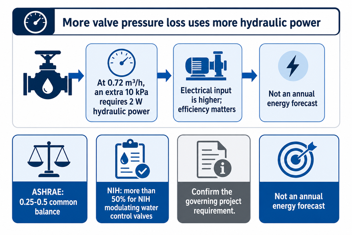
An authority figure of 0.50 is a conventional starting point for modulating valves but isn’t a general case acceptance value. The designer must reconcile project specifications with the installed characteristic and pressure budget. Increasing a valve loss from 10 kPa to 20 kPa requires justification beyond improving a ratio.
ASHRAE states 0.25-0.5 is a common balance between controllability and energy performance. NIH, on the other hand, states more than 50% is required for NIH modulating water control valves. These statements aren’t general case equivalences. A purchasing team should ask which project requirement governs, rather than average the figures or substitute one for the other.
The hydraulic trade-off is real. A valve must absorb some of the available pressure to regulate flow, but a larger pressure loss isn’t inherently a better design. At 0.72 m³/h, or 0.0002 m³/s, an additional 10 kPa requires 2 W of hydraulic power at that flow. Electrical input is higher and depends on pump and motor efficiency. This simple calculation is not an annual energy forecast: operating hours, diversity and pressure-reset behavior are still missing.
When a supplier says high authority is the only advantage of a smaller valve, ask for the full branch calculation. For hydronic fan coil units, a coil change can alter the remainder of the circuit enough to change the preferred coefficient.
A 10 kPa increase in valve loss at 0.72 m³/h adds 2 W of hydraulic demand in this example. Approve the pressure allocation only after checking the specified authority target and the pump operating point. A low-loss valve and a high-authority valve don’t win every comparison.
Choose a PICV or a conventional modulating control valve
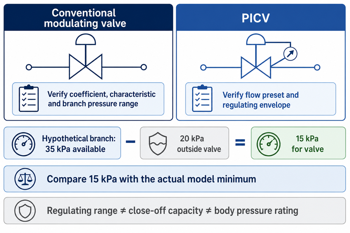
A pressure-independent control valve can regulate flow as system differential pressure changes, provided the selected model remains within its specified operating envelope. A conventional modulating control valve requires pressure management elsewhere in the system. Neither system can deliver 0.72 m³/h through a branch with insufficient pressure.
Conventional modulating valve
Consider it when the designer can establish a usable coefficient, installed characteristic and branch pressure range. Include the balancing arrangement and verify behavior at reduced load.
PICV
Consider it when changing branch pressure makes flow regulation difficult. Confirm flow preset range, minimum and maximum regulating differential pressure, and matched actuator close-off capacity.
ASHRAE’s 2020 valve guidance separates PICV regulating range from shutoff capability. A high close-off rating doesn’t mean the valve regulates accurately at that point. Similarly, a body pressure rating describes a different limit.
When not to buy a PICV as the first fix
Picture a commissioning contractor finding inadequate flow on the most remote fan coil. Replacing the existing valve with a PICV before measuring available differential pressure may preserve the fault. The new valve must have sufficient pressure to operate its regulator. Check the strainer, pump control and branch losses first, then evaluate the pressure available across the valve versus the pressure specified on the datasheet.
A PICV also cannot repair insufficient coil capacity, a wrong temperature sensor location or an actuator that receives the wrong control signal. Buying one solely to correct low water temperature difference is premature until airside duty and water flow are established. The CIBSE variable-volume systems module covers limits of operation and commissioning. Confirm the model’s approved measurement method; pressure taps do not automatically provide a valid flow reading.
For a hypothetical 35 kPa branch with 20 kPa consumed outside the valve, only 15 kPa remains for the valve. Compare that remainder with the actual PICV minimum at the requested flow setting. If the requirement exceeds 15 kPa, correct the pressure deficit before accepting the substitution.
Trace hunting through the valve actuator and control loop
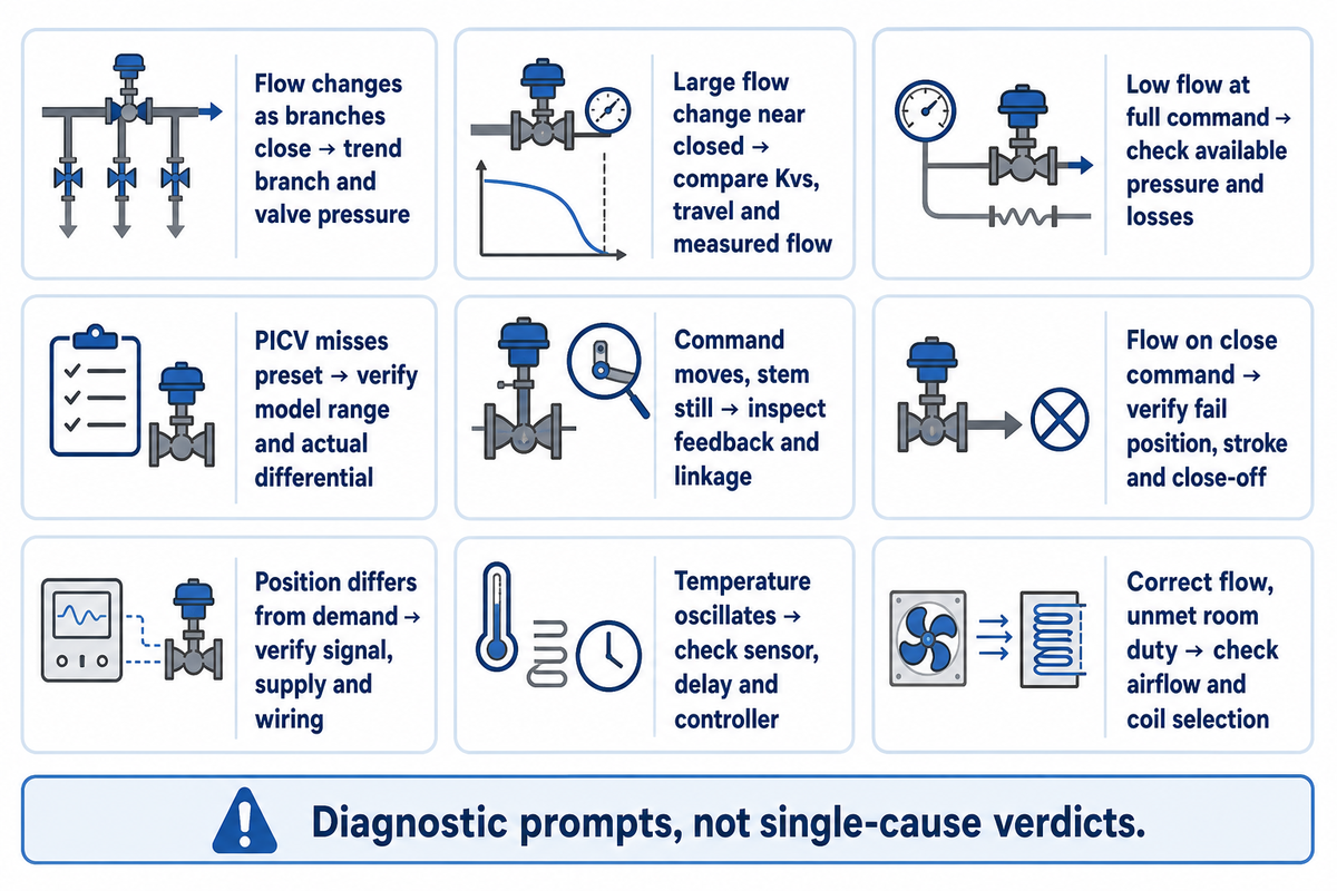
Valve hunting requires diagnostics that distinguish hydraulic behavior from actuator movement and temperature feedback. The NIH guidance on valve and control-loop interactions explains why component selection alone doesn’t resolve every control problem. Trend the control command and actual position if available, differential pressure, and coil temperature. A repeated 0–10 V command swing can originate in the loop; it does not by itself prove that the valve is oversized.
Use the following matrix to document your observations. Checks in the matrix are diagnostic prompts, not claims that every symptom has a single cause. Follow technical guides of the installed equipment before making setting changes. Specify the body and trim in a replacement request: a globe valve’s plug and seat arrangement must be appropriate for its intended function.
| Type | Observed symptom | Evidence to obtain | Decision and limitation |
|---|---|---|---|
| Hydraulic | Flow changes as other branches close | Branch and valve pressure trends | Review differential-pressure control; one static reading is insufficient |
| Hydraulic | Large flow change near closed position | Kvs, travel and measured flow | Check oversizing and characteristic; do not infer coefficient from DN |
| Hydraulic | Low flow at full command | Available pressure and component losses | Locate missing pressure or restriction before resizing |
| Regulating | PICV misses its preset flow | Model range and actual differential pressure | Confirm the regulating envelope before changing the preset |
| Mechanical | Command changes but stem stays still | Position feedback and linkage inspection | Check stiction or deadband; a hydraulic calculation cannot prove either |
| Mechanical | Flow persists on a close command | Fail position, stroke and close-off rating | Check assembly and seat condition; leakage may have several causes |
| Electrical | Position differs from controller demand | Signal type, supply and wiring | Verify compatible actuation before retuning |
| Control | Temperature oscillates after each movement | Sensor location, delay and controller settings | Review loop response with stable hydraulic conditions |
| Airside | Water flow is correct but room duty is unmet | Airflow, entering conditions and coil selection | Check terminal duty; authority alone cannot establish cooling output |
The procurement manager should require failure to be specified in the requisition. “Hunts at low load” is contextual information, but “command moves, stem sticks then jumps” warrants a different inspection. A pneumatic double-acting actuator also has different service requirements from an electric fan coil actuator; match the actual assembly.
For a 0–10 V modulating assembly, record command and measured response on a common time axis before adjusting controller gain. A valve that follows its command while temperature oscillates deserves a different investigation from a stationary stem. Leave the supplier’s deadband and stroke specifications next to the trend record. Severe noise should be checked separately; don’t assume that adjustment of the temperature loop would eliminate hydraulic or mechanical issues.
Match the coil duty to the valve selection

Coil duty determines the water flow used in valve selection; connection diameter can’t supply that value. Koven’s horizontal catalog lists 370, 850 and 2,210 kg/h for three different models of two-pipe, high-fan-speed chilled water coils. The series lists DN20 connections, which illustrates why mechanical fit isn’t sufficient.
| Model | Listed water mass flow | Procurement implication |
|---|---|---|
| KAFP-02WA | 370 kg/h | Request the matching coil pressure loss |
| KAFP-05WA | 850 kg/h | Recalculate coefficient for this duty |
| KAFP-14WA | 2,210 kg/h | Do not reuse the smaller model’s valve selection |
The horizontal fan coil specifications are manufacturer data, not independent test data. Mass flow in kg/h isn’t equal to volume flow in m³/h; converting one to the other requires density of the fluid at the specified condition. Don’t combine catalog airside static-pressure values with water pressure loss.
Cooling output does not generally change in direct proportion to water flow. ASHRAE’s hydronic system chapter discusses coil response to controller gain and the valve characteristic. As a result, two selections with equal authority can produce different temperature responses. Ask for the proposed valve characteristic with the coil selection, rather than assuming that a linear command gives linear heat transfer.
The series listed water flows from 370 to 2,210 kg/h share a DN20 connection. For the project, request the exact model, fan setting, water temperatures, and coil loss. The documented duty is the basis for the supplier’s valve recommendation; the connection drawing is just one part of the documentation.
Use the 3-Pressure Valve Selection Check in your RFQ
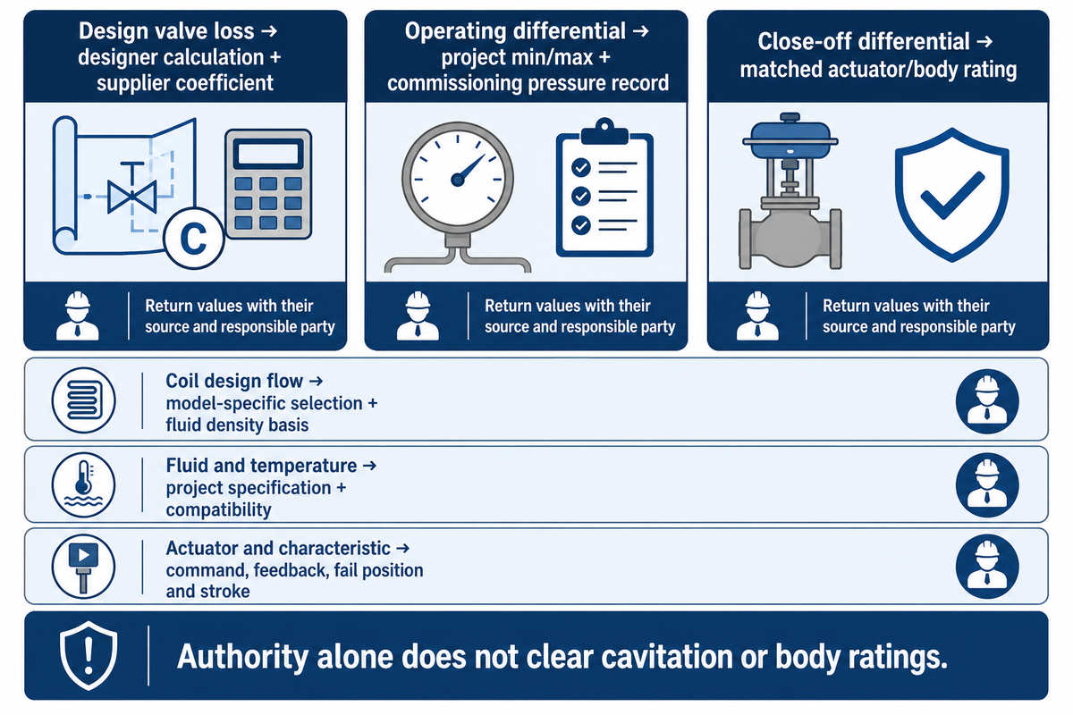
The 3-Pressure Valve Selection Check separates design valve loss, the operating differential pressure range, and the required close-off differential. Use it as a worksheet when requesting quotes for valve and actuator characteristics. For example, a 20 kPa design loss doesn’t establish either the minimum regulating pressure or the maximum pressure that the assembly can close off against.
Complete this checklist and include it in the RFQ. The ranges must be filled in based on the project and selected product; the example of 0.72 m³/h isn’t a recommended setting for every fan coil.
RFQ checklist: return values with their source and responsible party.
| Parameter | Recommended range | Why it matters | How to verify |
|---|---|---|---|
| Coil design flow | Project duty in m³/h or kg/h; example 0.72 m³/h | Sets required capacity | FCU supplier returns model-specific selection and fluid density basis |
| Design valve loss | Calculated kPa; example 20.25 kPa at Kvs 1.6 | Sets authority with the circuit remainder | Designer supplies full branch calculation and valve supplier confirms coefficient |
| Operating differential | Project minimum and maximum in kPa, within model limits | Tests regulation across changing loads | Designer predicts range; commissioning contractor records pressure at agreed taps |
| Close-off differential | Assembly rating in kPa at least equal to maximum anticipated shutoff differential | Prevents pressure forcing the valve open | Valve supplier returns matched actuator/body rating |
| Fluid and temperature | Project glycol percentage and minimum/maximum °C | Changes sizing and material requirements | Designer supplies fluid specification; supplier confirms compatibility and rating |
| Actuator and characteristic | Project signal, such as 0–10 V, plus specified flow characteristic | Connects hydraulic selection to the control sequence | Controls contractor verifies command, feedback, fail position and stroke |
The University of Maryland Division 23 requirements provide a good illustrative example for documenting Cv, design flow, pressure drop, close-off, characteristic and turndown. The worksheet isn’t a project specification or a new industry standard.
Absolute pressure and vapor pressure require a separate cavitation check. Also verify body pressure/temperature ratings and materials. An authority calculation can’t clear these requirements. If a quote omits the operating range, return it for completion, even if the unit price is attractive.
Integration requirements for variable-flow HVAC systems
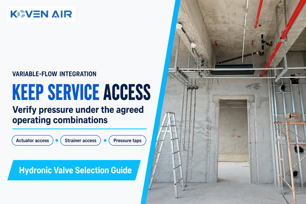
Variable-flow integration requires pressure control that supports the hydraulically critical terminal without imposing unnecessary differential pressure elsewhere. Confirm the coil duty, valve operating envelope and pump sequence. An illustrative 15 kPa remaining across a PICV is acceptable only if the actual model can regulate at that pressure and requested flow.
During a staged office refurbishment, some branches may use conventional valves while others use PICVs. The commissioning contractor should test the agreed operating combinations, rather than assume satisfactory flow with every branch open proves satisfactory part-load operation. Note the state of the other valves and pump mode with each measurement.
A concealed terminal should have access to the actuator, strainer and pressure taps. The concealed fan coil unit guide helps with enclosure and service route. A valve that can be selected on paper but can’t be viewed or removed creates a maintenance issue. Residential and commercial projects both need product selection help tied to their drawings, rather than a list of generic design solutions.
Suppliers citing IEC 60534-2-1 should identify the sizing method and assumptions used. A standard reference alone is not a certificate for the complete fan coil installation. Obtain the coefficient, installed corrections where relevant and the permissible operating conditions with the quotation.
Before ordering: establish coil duty, calculate the defined branch, verify the valve’s operating limits and match its actuator. For Koven fan coil units, send the required capacity, water temperatures, fluid specification and available branch pressure with your selection request.
Frequently asked questions
What is a good valve authority?
For a standard modulating hydronic valve, about 0.5 is a common design starting point, rather than a universal pass mark. Check the selected manufacturer’s guidance, the defined circuit boundary and changing differential pressure. Good authority alone can’t correct poor actuator resolution, faulty temperature sensing, or incorrect controller tuning. Document all checks done along with the sizing calculation.
What is the difference between Inherent and Installed characteristics?
The inherent characteristic describes how a valve’s flow coefficient changes with travel under a constant differential pressure test condition. The installed characteristic includes the surrounding circuit, where flow and pressure change together. Therefore a curve printed in a valve catalogue doesn’t, by itself, predict the response of the complete fan coil control loop. Distorted installed flow characteristics describe that departure from the valve’s constant-pressure test curve.
Is Valve Authority related to Valve Stiction?
They may display similar symptoms, but describe different conditions. Authority concerns the hydraulic pressure allocation; stiction is friction that resists smooth valve movement. Compare control command, actual stem position and flow before deciding which problem exists. Replacing an oversized valve won’t correct a sticking actuator linkage, and adjustment alone won’t remove mechanical friction.
What is a 2-position actuator?
A two-position actuator drives a valve between two commanded states, usually open and closed. It can’t provide a continuously varying control. Prior to specifying the matched valve/actuator assembly, determine if the fan coil sequence requires on/off, floating or modulating control.
Can a PICV work when available pressure is too low?
A pressure-independent control valve requires a model-specific minimum differential pressure to operate correctly. First subtract coil and branch accessory losses from available branch pressure at the required flow. Compare the pressure across the valve with the manufacturer’s operating envelope. If pressure is insufficient, examine the pump setting, restrictions and circuit design. Increasing the valve preset cannot create missing pressure. Also check maximum regulating pressure and the matched assembly’s close-off rating separately. Record the pressure measurement locations so the commissioning contractor can reproduce the check at the hydraulically critical terminal under the stated operating condition.
Does a larger connection mean a larger required Cv?
No. The connection diameter of coils defines a mechanical interface and Cv defines the flow capacity under defined conditions. Therefore, two coils with the same connection can require different design flows. Select the valve coefficient from duty and pressure data, and then verify connection arrangement.
Should a three-way valve bypass be ignored in the calculation?
No. A three-way mixing or diverting arrangement creates a different hydraulic boundary from a simple two-way branch. Locate both flow paths, determine pressure losses and intended operation of the pump. Follow the valve manufacturer’s application diagram and balance the bypass where that design requires it. Do not transfer the two-way worked example unchanged, or assume that a three-way valve is immune to authority problems. Have the system designer confirm the circuit model before selecting the assembly. A bypass diagram, design flows in both legs and the method of balancing give the supplier a clearer basis than a connection size alone.
References & Sources
- NIH Office of Research Facilities, Design Considerations for Modulating Hydronic Control Valves, September 2024. Institutional selection and control guidance.
- ASHRAE Handbook, HVAC Systems and Equipment, Chapter 46: Valves, 2024 and 2020 editions. Publicly accessible sections cited above.
- ASHRAE Handbook, Chapter 13: Hydronic Heating and Cooling, 2020. Coil, valve and controller response.
- IEC 60534-2-1:2011 and IEC 60534-2-3:2015. Public catalog scopes; full paid standards were not used.
- CIBSE Journal, variable-volume systems CPD module, January 2019. Operating and commissioning context.
- University of Maryland, Division 23: HVAC. Control-valve schedule and submittal requirements.