
Get in Touch with Koven Air Company


![Cleanroom Dry Cooling Coil: How It Works [2026 Guide]](https://kovenair.com/wp-content/uploads/2026/07/cleanroom-dry-cooling-coil-guide-featured-2.png)
Updated: July 2026.
A cleanroom dry cooling coil is a heat exchanger that cools recirculated air in a cleanroom using chilled water, engineered so the coil’s surface temperature never drops below the room’s dew point — abbreviated DCC in the rest of this guide. Since dew-point physics is well documented in ASHRAE’s own HVAC Systems and Equipment Handbook, the reason a DCC remains “dry” is nothing more than simple psychrometrics applied intentionally.
This guide walks through what a DCC actually does, how the dew-point margin works, where it resides within a cleanroom’s air-handling system, and what changed in 2026 that buyers specifying one should understand. Know what it is and want to spec out a unit for your facility? Our Cleanroom Dry Cooling Coil selection guide covers ISO Class 5-8 sizing and material selection in more depth than this guide does.
Quick Specs
| What it does | Removes sensible (temperature) heat only — no dehumidification |
| Typical supply / return water temp | 13°C / 18°C (industry convention — not an ASHRAE-mandated figure, see H2-2) |
| Where it’s installed | Return-air plenum or ceiling void, alongside MAU and FFU |
| Typical applications | Semiconductor fabs, pharmaceutical/biotech cleanrooms, precision electronics assembly |
| Governing energy code reference | NYC Energy Conservation Code 2025 §6.5.4.7 (chilled-water coil temperature-differential rule) |
What Is a Cleanroom Dry Cooling Coil?
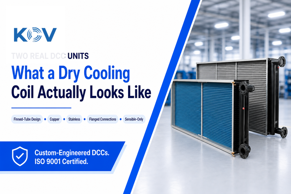
In the world of cleanroom HVAC, the dry cooling coil is a finned-tube heat exchanger — commonly manufactured with copper tubes and aluminum fins, effectively a specialized indoor air cooler — that circulates chilled water and uses its heat-exchange surface area to capture heat from the air blowing over it.
It’s “dry” not in terms of construction but operation: the chilled-water supply is kept warmer than the room’s dew point, so the coil surface never dips below that threshold and doesn’t sweat.
That difference matters nearly everywhere, but nowhere more than inside a cleanroom. Standing condensate on a coil is a potential risk for both microbial growth and particle shed — two no-nos in a classified space. Standard cooling coils handle both humidity and temperature simultaneously; they cool air below the dew point on purpose, so moisture condenses out and gets removed as part of dehumidification.
Dry coils are purposefully narrower in scope: they handle only temperature, and the humidity problem falls to a make-up air unit. (We’ll come back to this below).
“Even within the same manufacturer’s own product catalog, dry cooling coil pages sometimes get described with generic cooling-coil marketing copy that mentions dehumidification — which is precisely the function a true dry coil is designed not to perform. If a spec sheet for a cleanroom DCC lists dehumidification as a feature, that’s worth a follow-up question to the vendor before you buy.”
— Industry observation, based on a documented case of exactly this labeling inconsistency on a manufacturer’s own site
How Does a Dry Cooling Coil Actually Work? (The +2°C Margin Convention)
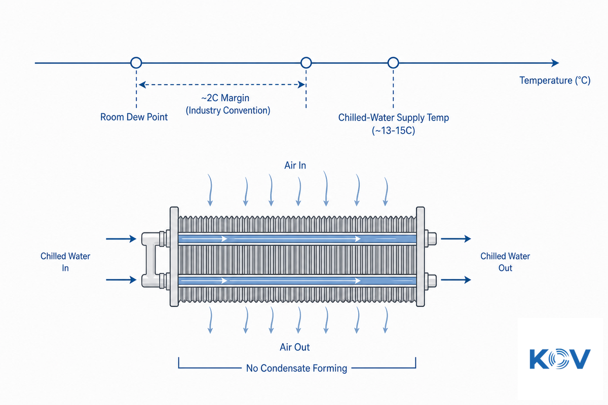
Get the supply water temperature wrong on a DCC and the failure mode isn’t subtle — the coil starts sweating, and in a classified space that means an unplanned contamination investigation, not just a comfort complaint. Understanding the mechanism below is what lets a buyer sanity-check a vendor’s proposed setpoint before it ships, rather than finding out during commissioning.
WHAT: A DCC removes sensible heat (the heat that raises air temperature) and nothing else. WHY: it does this by keeping the chilled-water supply above the room air’s dew point, so the coil surface never gets cold enough to trigger condensation. SO WHAT: the net effect is a coil that cools without dehumidifying — precisely what a cleanroom needs from this piece of equipment.
Industry convention is to supply water around 13°C and return around 18°C, with the supply temperature set roughly 2°C above the calculated room dew point. That number is worth a brief explanation of what it is and isn’t. The underlying psychrometric theory is solid — condensation begins exactly at the dew point, a value that depends on air pressure and humidity, and that is well documented by ASHRAE. What we couldn’t find was a published ASHRAE standard for the specific “+2°C” margin; it appears to be a consistent industry design convention, found independently on two manufacturer websites. Treat it as a reasonable starting point, not a hard-and-fast rule.
📐 Engineering Note — Worked Example
Say a cleanroom runs at 22°C and 55% relative humidity. Based on standard psychrometric relationships, the dew point at that condition is roughly 12.6°C. Applying the ~2°C convention gives a target supply water temperature of about 14–15°C, with return water typically 4–5°C higher depending on flow rate and load. Run the same calculation with your own facility’s actual design temperature and humidity before specifying a supply temperature — the 13°C/18°C figures quoted across the industry are a starting reference, not a substitute for your site’s own numbers. This tight a margin also leaves little room for sensor drift, calibration error, or coil surface non-uniformity; most engineers build in an additional field tolerance buffer beyond the theoretical margin.
Why Doesn’t a Dry Cooling Coil Produce Condensate?
Condensation happens when a surface drops below the surrounding air’s dew point, giving moisture nowhere to go but onto the cold surface. Properly designed dry coils avoid this by keeping water temperature above the dew point, so the coil surface never reaches that threshold regardless of how long the system runs. That’s the opposite of a conventional wet coil, which runs below dew point on purpose so moisture condenses out.
A 2024 Purdue University study on cooling-coil condensate behavior confirmed that once a coil surface drops below dew point, condensate formation follows predictably from air pressure and humidity, exactly as psychrometric theory describes — the physics is well established, even though the DCC’s specific margin above it is an industry convention rather than a codified standard.
Where DCC Fits in a Cleanroom HVAC System, MAU + FFU + DCC
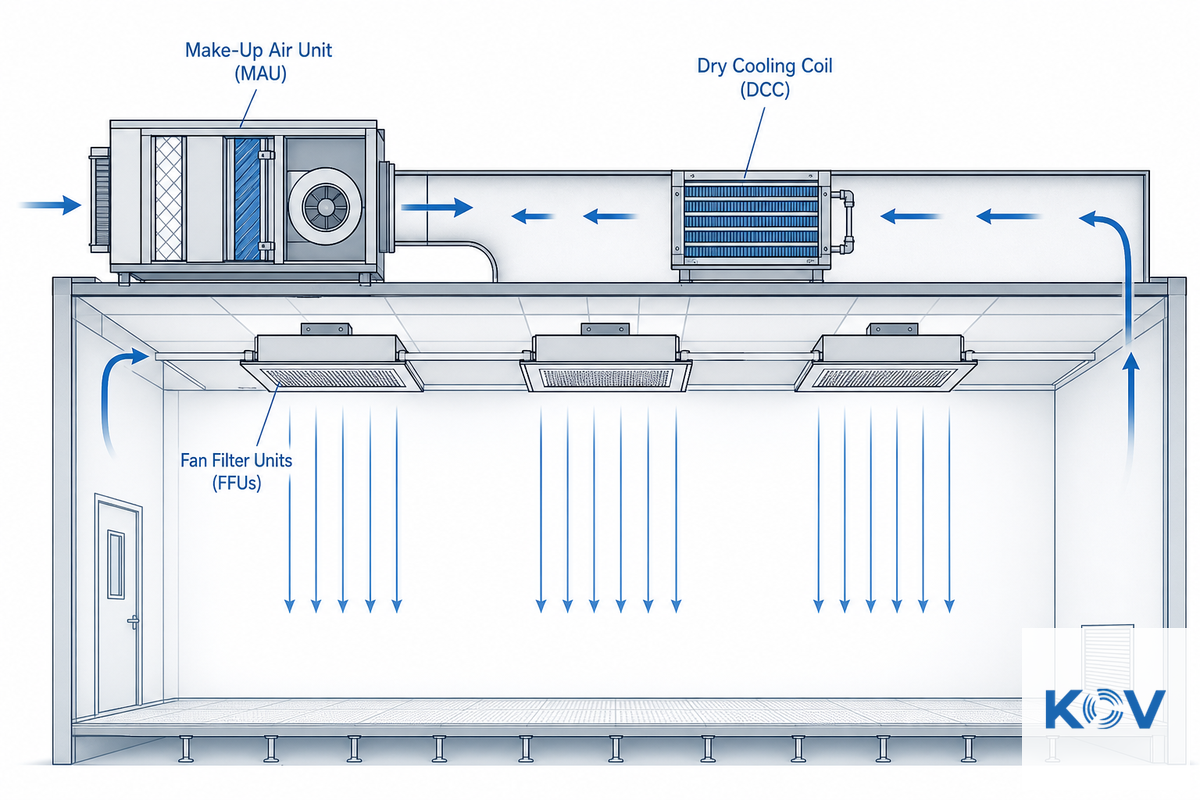
Rather than a standalone air conditioner, a dry cooling coil works as one piece of a cleanroom’s 3-component constant temperature-and-humidity system, as described independently by both a manufacturer technical page and a 2025 peer-reviewed cleanroom-HVAC review: a make-up air unit, a fan filter unit, and the dry cooling coil itself, each handling a distinct, non-overlapping part of the environmental control job rather than one unit trying to do everything at once:
- ✔MAU (Make-Up Air Unit): responsible for supplying outside fresh air, handling filtration and the system’s latent load (humidity).
- ✔FFU (Fan Filter Unit): installed in the ceiling grid with particulate filtration, maintains vertical airflow — it doesn’t influence temperature or humidity.
- ✔DCC (Dry Cooling Coil): installed in the return-air stream, removes sensible heat from equipment and occupants without affecting humidity.
Dividing the job in this way – instead of using one coil to both remove heat and humidity, as a standard commercial AHU does – side steps an often significant source of energy waste: chilling air so far that it dehumidifies the air and then warming it up again to reach the target temperature. (In that regard, a 2025 peer-reviewed study on cleanroom environmental control strategies refers to such load separation as current best practice in cleanroom hvac energy efficiency research; it’s not a static technology).
Given that a DCC is most effective when incorporated into such a system, it makes sense to evaluate how the unit would integrate with your facility’s make-up air unit and cleanroom air handling unit prior to viewing it as a discrete purchase decision.
Dry Cooling Coil vs. Conventional Wet/DX Coils, What Changes
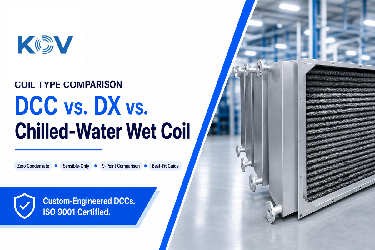
What Is the Difference Between Wet Coil and Dry Coil?
The most concise definition we could find wasn’t from a manufacturer but rather a working HVAC technician responding to a query on a trade forum: “A dry cooling coil removes sensible heat from the air stream. A wet coil removes sensible and latent heat (moisture) from the air stream.”
That same thread — still actively referenced years after it was first posted — shows the distinction trips up non-cleanroom professionals too; it’s a general HVAC concept, not a specialized cleanroom one.
| Attribute by Coil Type | Dry Cooling Coil (DCC) | DX (Direct Expansion) Coil | Conventional Chilled-Water (Wet) Coil |
|---|---|---|---|
| Handles humidity? | No — sensible only | Yes — condensing by design | Yes — condensing by design |
| Typical water/refrigerant temp | ~13°C supply / 18°C return water | Refrigerant, evaporates ~4–10°C | Chilled water, commonly ≥15°F (8.3°C) supply/return differential |
| Typical install location | Return-air plenum or ceiling void | Indoor air-handler or standalone unit | Central AHU coil section |
| Condensate management needed? | No (safety drain pan only, by design) | Yes — dedicated condensate drain required | Yes — dedicated condensate drain required |
| Requires a separate humidity-control unit? | Yes — paired with a make-up air unit | No — handles both in one coil | No — handles both in one coil |
| Reheat energy penalty? | None — no over-cooling to reverse | Possible if dehumidifying below target temp | Possible if dehumidifying below target temp |
| Typical service scale | Cleanroom-scale recirculated sensible load | Standalone or smaller AC units | Central-plant commercial AHUs |
| Contamination risk from condensate? | Effectively none, by design | Standard condensate risk (non-issue outside classified spaces) | Standard condensate risk (non-issue outside classified spaces) |
| Best fit | Cleanroom recirculated-air sensible load | Standalone or smaller AC units, non-cleanroom spaces | General commercial AHUs where dehumidification is wanted |
Key Factors to Consider
- If the process require near-zero condensate tolerance (a particle-sensitive space, or one with GMP classification) – then the DCC is the answer, combined with a separate MAU for humidity.
- If humidity control is as critical as temperature and the space isn’t classified – then the conventional wet coil will suffice to do both, though at the expense of reheat.
- For small, self-contained, non-cleanroom rooms – the DX coil will be the least expensive choice, even relative to any type of chilled-water system.
Note one of the primary operating differences: a standard wet coil evaporator is often run 19°C to 20°C below the return-air temperature of the air stream being cooled (the same trade-forum technician suggested, “the evaporator coil should run approximately 35°F colder than the return air temp”). In contrast, the DCC stays very close to the space condition, its operation determined by the set dew-point margin rather than how cold it can be driven. Unlike heat pump chillers or active chilled beams (which condition the space directly and are mounted within it), a DCC is located out of the occupied space in the return-air duct or ceiling plenum.
Chilled Water Design Parameters That Keep a Coil “Dry”
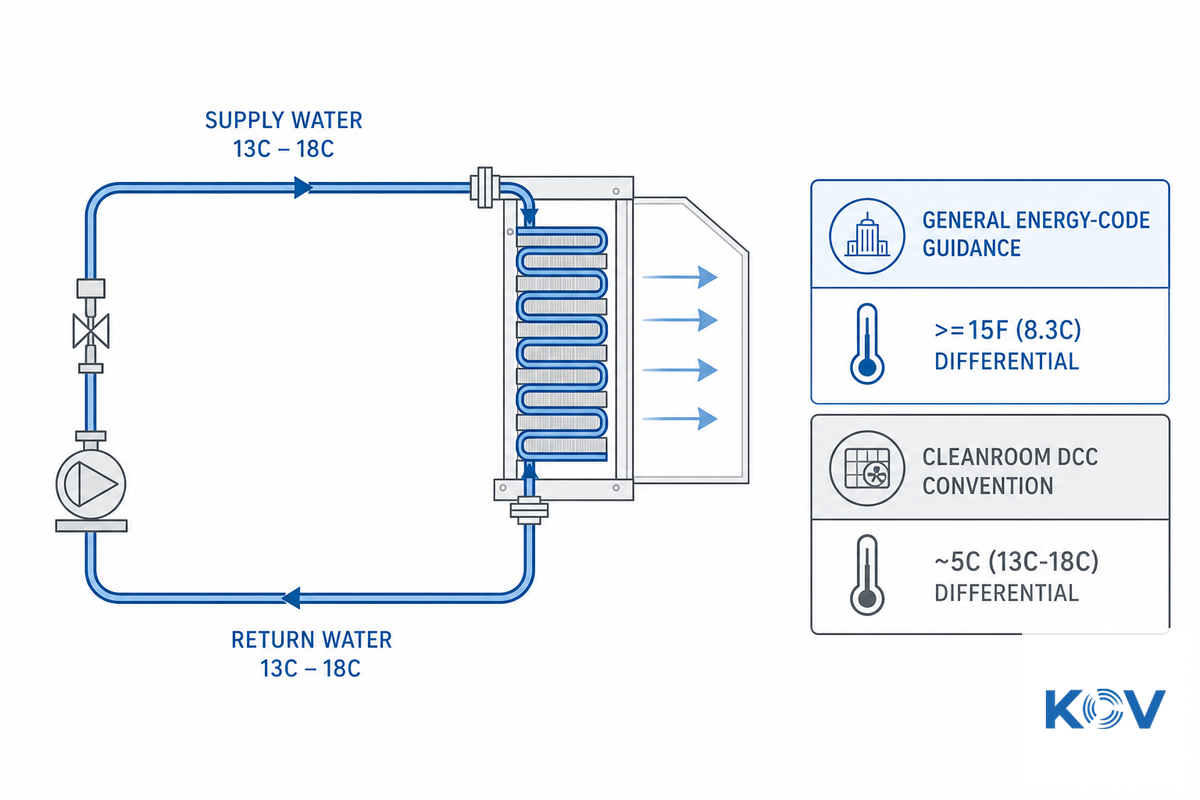
There are several design trade-offs in addition to the dew-point margin already noted that come into play before a chilled-water plant gets sized for a DCC. Many general building energy codes push for a greater supply-to-return differential in chilled water, since a bigger delta-T means less water needs to be pumped for the same cooling load — which saves pump energy. Per UpCodes’ rendering of New York City’s 2025 Energy Conservation Code, for example, chilled-water cooling coils are required to be selected for a temperature differential of 15°F (8.3°C) or higher between leaving and entering water, with a minimum 57°F (13.9°C) leaving water temperature at design conditions, subject to several listed exceptions — verify current wording against the official NYC code text for your specific jurisdiction before treating it as a compliance citation.
By comparison, a cleanroom DCC normally operates at a much smaller differential — on the order of 5°C (13°C to 18°C) by convention. This isn’t an accident; it’s a direct result of the dew-point constraint described above. The supply temperature has a firm floor here — it can’t drop below the room’s dew point, or you start making condensate.
This limits how wide the differential can be pushed without either raising the return temperature (reducing cooling capacity) or accepting a smaller delta-T than a general-purpose energy code would prefer. This tension — energy-code efficiency guidance pulling one way, dew-point safety pulling the other — is a real, if unglamorous, category of design tradeoff. It shows up under the name “low delta-T syndrome” in cooling-coil engineering literature, where selecting a coil with a lower delta-T than the chilled-water plant is designed around is flagged as one of the most common coil-selection errors — worth checking explicitly with whoever is sizing the plant.
For ISO Class-specific coil sizing that accounts for cleanliness level alongside these thermal parameters, see the detailed selection tables in our cleanroom dry cooling coil solution guide — this article covers the underlying thermal design logic, that one covers ISO Class 5–8 selection specifics.
Where Cleanroom DCC Systems Are Actually Used

Cleanroom dry cooling coil solutions show up wherever a space needs tight, stable temperature control without disturbing humidity or risking particle contamination from condensate — semiconductor fabs, pharmaceutical and biotech manufacturing, and precision electronics assembly are the three application groups this guide’s research turned up most consistently, but the underlying reason DCC matters differs meaningfully by industry, as the two cards below explain:
Semiconductor Manufacturing
Demands very tight temperature and particle control (commonly cited around ±0.1°C and ±1% RH by DCC manufacturers), driven by process yield sensitivity to thermal drift rather than a formal compliance framework in the way pharma is. On the energy side, a 2025 peer-reviewed study on chilled-water and supply-air distribution for semiconductor cleanroom cooling found that this kind of sensible/latent-load separation contributes to measurable energy-saving potential in fab-scale cooling systems — a topic no competitor content we reviewed for this guide cited.
Pharmaceutical & Biotech
Driven primarily by GMP aseptic-processing requirements and contamination-control standards rather than thermal precision alone. Note: ISO 14644-1 itself classifies airborne particle concentration specifically — it does not cover physical, chemical, radiological, or viable contamination on its own. A DCC supports the environmental stability that an ISO-classified space needs, but particle classification itself comes from filtration and airflow design (FFU), not from the cooling coil.
As thermal stability requirements of semiconductor manufacturing and aseptic processing in pharmaceutical operations follow very different logical pathways and regulatory schemes, you may want to confirm which factor is truly dominant for your particular space before concluding a single “cleanroom grade” spec covers both.
Common Problems and Maintenance Considerations
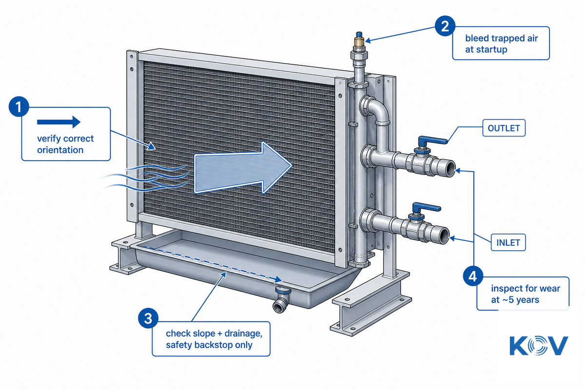
When a dry coil isn’t working as you might expect, it’s often a matter of one of a few standard problems that are catchable at commissioning or through routine checks, not after a breakdown.
- Low heat transfer as a result of incorrectly oriented airflow.
If water doesn’t flow in the intended direction through the airflow on the coil, then thermal-transfer efficiency will be lowered-this should be discovered during commissioning and isn’t a defect of the unit itself.
- Trapped air in coil during start-up.
Air is usually purged from the coil during start-up; otherwise, it may impede proper water flow, creating a block in the heat exchange.
- Incorrect slope of drain pan.
Many coil, even those described as “dry,” still include a safety pan for the collection of condensate should one occur, which must be sloped correctly so that any collected water will drain off properly.
- Slag remaining in water circuit.
Weld slag is a known contaminant in some copper plumbing that, with time and water contact, will break down from contact with the pipe wall and eventually contribute to leaks or ruptures.
Routine maintenance on a DCC is comparatively light precisely because a properly functioning coil produces no condensate to manage — but “properly functioning” is the operative phrase.
Basic checks on your coil can be built into a routine maintenance schedule to help avoid those occasional surprises. They include confirming that airflow velocity across the face of the coil is within specification, that the temperature margin between inlet and outlet water temperatures is stable and hasn’t eroded over time toward the dew point, checking the condensate drain pan for the accumulation of any liquid or solid debris, and, every 5 years or so, examining inlet and outlet water valves for any wear that could lead to a leak. None of this involves disassembly and should take just a few minutes with simple tools.
Industry Outlook, What’s Changing for Cleanroom Cooling in 2026

A facilities engineer who specs a chilled-water plant today and assumes today’s refrigerant rules will still apply in year 12 of a 15-year service life is taking on real compliance risk — refrigerant regulations have moved every year since 2022, and a plant sized around a refrigerant that becomes restricted mid-life can mean an expensive retrofit, not just a paperwork update. Market-size numbers around HVAC generally point in a familiar direction — the global HVAC systems market is projected to grow from roughly $299 billion in 2025 to around $408 billion by 2030, a figure that’s directional context rather than something specific to cleanroom cooling or worth building a purchasing decision around on its own.
A more concrete driver for anyone specifying equipment with a 15+ year service life is the ongoing U.S. phase-down of HFC refrigerants under the AIM Act, and it’s more subsector-specific than a single headline date suggests. The EPA’s overall target is reducing regulated HFCs to 15% of historic baseline levels by 2036, phased in steps – but the equipment-restriction dates vary meaningfully by application: comfort-cooling chillers fall under an earlier restriction window, industrial-process chillers (the category most relevant to a DCC’s supporting chilled-water plant) are affected starting in 2026, and small-charge semiconductor manufacturing equipment has its own later 2030 date – which the EPA proposed extending further in 2025 for several affected subsectors, semiconductor manufacturing included. Separately, a January 1, 2026 restriction limits reclaimed-refrigerant sales to no more than 15% virgin HFC content by weight for the specific refrigerant categories covered under 40 CFR Part 84 Subpart C — the exact scope varies by refrigerant type and equipment category, so confirm applicability against the current EPA regulation text (not a secondhand summary) for your specific chilled-water plant’s refrigerant.
A May 2026 Federal Register rule also reconsidered certain Technology Transitions requirements – worth checking directly against your equipment’s specific subsector before assuming any single date applies, rather than treating 2026 as a uniform cutover.
For a buyer specifying a chilled-water plant that will feed a DCC system for the next decade or more, the practical takeaway isn’t a single date to circle on a calendar – it’s confirming which subsector classification your facility’s chiller equipment falls under, and checking that classification against the current EPA schedule (not a 2025-era assumption) before finalizing refrigerant selection.
FAQ
Q: What is a dry cooling coil?
View Answer
A dry cooling coil (DCC) is a heat exchanger that cools recirculated air using chilled water without letting the coil surface drop below the air’s dew point. Because the coil stays “dry” – no condensate forms – it removes only sensible heat (temperature), not latent heat (moisture).
That’s the core distinction from a conventional AC coil.
Q: What is the difference between a wet coil and a dry coil?
View Answer
A wet coil (standard AC/DX coil) is deliberately run below the air’s dew point so it condenses and removes moisture along with heat – that’s how conventional air conditioning dehumidifies.
A dry coil is run above the dew point on purpose, so it removes heat only and leaves humidity untouched. In a cleanroom, humidity is usually controlled separately by a make-up air unit, so the DCC’s job is narrower by design.
Q: What is a dry coil unit in a clean room?
View Answer
In a cleanroom, a dry coil unit is typically installed in the return-air path or ceiling void to absorb the sensible heat load thrown off by process equipment, lighting, and people – without touching humidity, which the make-up air unit already controls. Running it “dry” (above dew point) also avoids the microbial growth and particle-shedding risk that standing condensate would create inside a classified space.
Q: How does a dry cooling coil avoid condensation?
View Answer
By keeping the chilled-water supply temperature a margin above the room’s dew point – commonly cited around 2C higher – so the coil surface never cools below the point where moisture drops out of the air.
Q: Can a dry cooling coil be retrofitted into an existing cleanroom AHU?
View Answer
Generally yes, if there is additional coil section capacity available in the AHU, and the chilled-water plant can provide the higher (dry-running) temperatures, but an engineering assessment is required, not a direct substitution.
Q: What are the two main cooling coil types?
View Answer
Wet (condensing/DX) coils and dry (sensible-only) coils.
References & Sources
- EPA — Frequent Questions on the Phasedown of Hydrofluorocarbons — U.S. Environmental Protection Agency
- Phasedown of Hydrofluorocarbons: Reconsideration of Certain Regulatory Requirements (2026-05-26) — Federal Register
- Investigation on Condensate Temperature from Cooling Coil (Stusynski & Yu, 2024) — Purdue University International Refrigeration and Air Conditioning Conference
- Integrating the distribution of chilled water and supply air for energy-saving semiconductor cleanroom cooling (2025) — ScienceDirect, Applied Energy
- Energy Efficiency Optimization of Air Conditioning Systems Towards Low-Carbon Cleanrooms — A Review (2025) — MDPI Energies
- Chilled-Water Coil Selection §6.5.4.7 — NYC Energy Conservation Code 2025 (UpCodes)
- Cooling Coil — an overview — ScienceDirect Topics
Why We Write This
Koven Air has manufactured commercial, cleanroom, and industrial HVACR equipment — including dry cooling coils — since 2007, exporting to more than 35 countries.
This guide was created because the available online explanations of dry cooling coils don’t go beyond the manufacturer definition and fail to address the fundamental dew point science, chilled water design tradeoffs, and the impending 2026 refrigerant restrictions which impact long term purchases. We’ve sourced material from external authorities where indicated.
Reviewed by the Koven Air technical team

![Cleanroom HVAC Systems: ISO Classes & Design Guide [2026]](https://kovenair.com/wp-content/uploads/2026/07/cleanroom-ahu-pharma-biotech-guide-featured-2-768x512.png)


![Commercial Rooftop Unit Guide: Types, Sizing & Costs [2026]](https://kovenair.com/wp-content/uploads/2026/07/commercial-rooftop-unit-guide-featured-2-150x150.png)