Get in Touch with Koven Air Company

Quick Specs
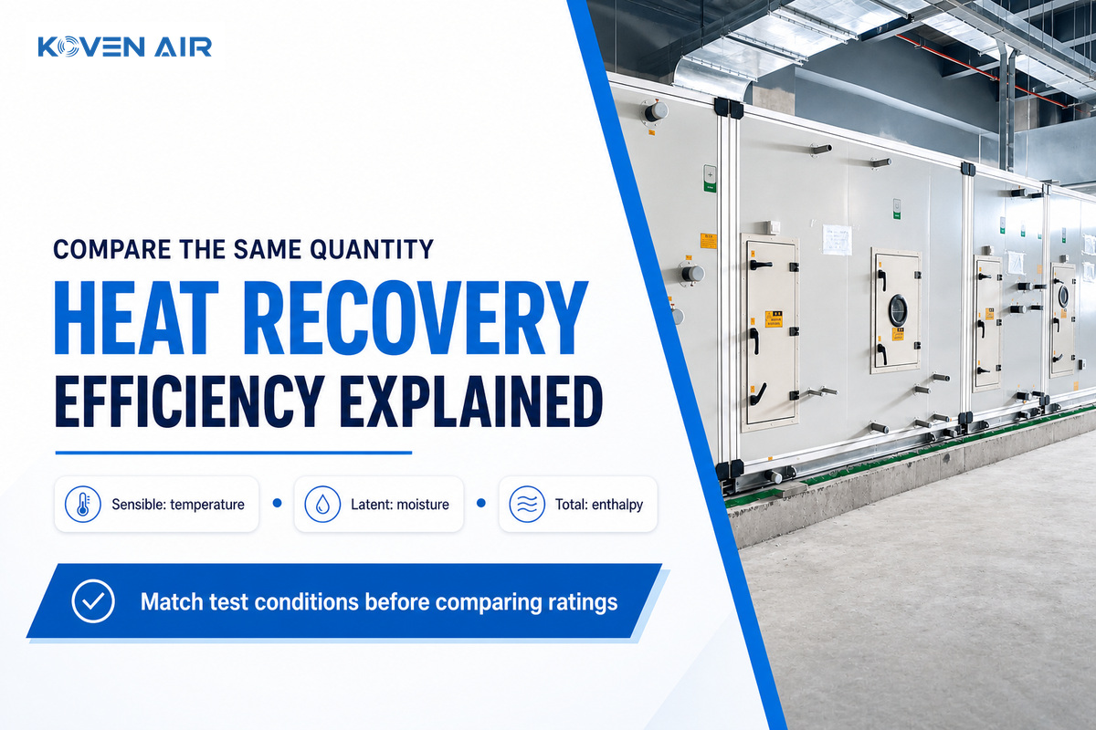
Heat recovery efficiency describes a stated energy-transfer ratio. Compare the same quantity, airflow and test conditions. Sensible recovery concerns temperature; latent recovery concerns moisture; total recovery concerns enthalpy. Example temperature ratio: 75% at −5°C outdoor air and 22°C return air gives 15.25°C leaving supply air.
One supplier’s 80% heat recovery efficiency could be different from another supplier’s 75%. One may define a dry core temperature ratio while the other includes fan energy and leakage adjustments. Buying the higher of the two may leave the facilities team with higher electrical demand with no comparable performance guarantee.
Heat recovery efficiency is a stated measure of energy transfer between air streams. Sensible, latent and total ratings measure different quantities. Compare matching test conditions, then account for fan power and controls before estimating savings.
Key takeaways
- A more effective core can save less purchased energy if its extra pressure loss raises fan demand too far.
- A temperature ratio can’t establish latent or total energy recovery.
- Fan-adjusted unit ratings must not be inserted into a core calculation that subtracts fan energy again.
- Equal airflow doesn’t establish equal footprint, certification or annual savings.
What Does Heat Recovery Efficiency Measure in Energy Recovery?
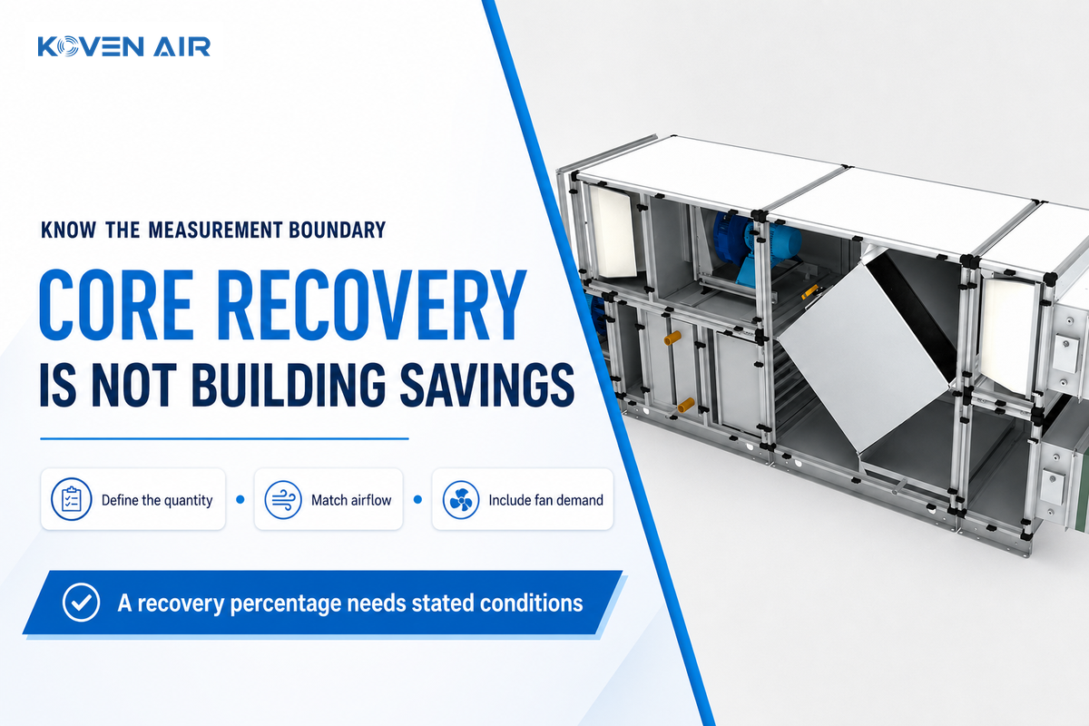
Heat recovery efficiency defines the quantity of a stated transfer opportunity that a device captures under specified conditions. This quantity can be temperature change, moisture transfer, or total air energy. An efficiency percentage is useful only if its definition, airflow basis and equipment limits are included.
In ventilation, a heat exchanger uses exhaust air to precondition incoming fresh air. Sensible heat recovery captures heat from the exhaust air. A suitable energy recovery device can transfer both sensible and latent heat. Its core exchanges heat and moisture based on its construction and operating conditions. Its purpose is to recover energy that would otherwise leave with the stale air. The U.S. Department of Energy’s ventilation overview explains this distinction for residential ventilation devices. Transfer quantities assist in describing commercial recovery. The transfer quantities also help explain commercial recovery, although the rating scheme and installation requirements must match the application.
Recovery reduces part of the heating energy demand required for replacing indoor air with outside air. That reduction in ventilation heat loss doesn’t establish whole-building energy efficiency. Proper ventilation still demands the particular air quantity and distribution. Recovery doesn’t give the required outdoor air exchange rate or confirm indoor air quality. This isn’t the same as calculating industrial waste heat recovery from a furnace or combined heat and power plant.
Common mistake: A common mistake is treating a percentage as a building saving. A stated 75% sensible effectiveness on a 20 K inlet temperature difference indicates a supply side rise of 15 K at equal dry-air heat-capacity rates. The remaining heating load, fan demand and operating hours need to be calculated as well. A buyer who assumes “75% energy savings” should ask what energy denominator was used.
Sensible, Latent and Total Ratings: Compare the Same Quantity
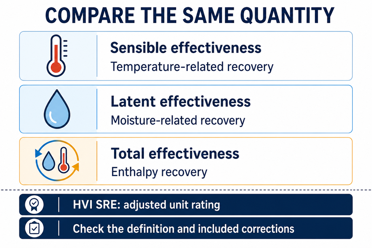
Sensible and latent ratings aren’t interchangeable. Total ratings are also not interchangeable with sensible or latent ratings. A stated total heat recovery percentage can’t be reconstructed by averaging sensible and latent percentages, because their contributions depend on the conditions of the inlet air.
What Is Sensible Recovery Efficiency?
In the Home Ventilating Institute (HVI) scheme, Sensible Recovery Efficiency (SRE) is defined as a specific unit rating. It accounts for certain effects including electrical consumption, leakage and imbalance. A supply-air temperature ratio doesn’t reproduce that. Ask the supplier which definition of SRE they’re quoting.
The HVI ventilation glossary explains these. The builders’ guide to HRV and ERV metrics explains that Adjusted Sensible Recovery Efficiency (ASRE) serves energy models that account for fan input separately. It’s different from the glossary’s Apparent Sensible Effectiveness (ASEF) and shouldn’t be substituted for an unadjusted core rating.
If an offer specifies enthalpy efficiency, demand the definition of the total-recovery figure. The same for sensible heat efficiency. The efficiency of an ERV isn’t a single universal metric.
3-Rating Comparison Sheet
A worksheet that allows the buyer to separate the recovered quantity, set the calculation boundary and provide evidence before two efficiency figures can be compared.
| Offer field | What it describes | Required comparison evidence |
|---|---|---|
| Sensible effectiveness | Temperature-related recovery | Formula, mass-flow basis and inlet temperatures |
| Latent effectiveness | Moisture-related recovery | Humidity ratios and mass-flow basis |
| Total effectiveness | Enthalpy recovery | Inlet enthalpies and tested airflows |
| HVI SRE | Adjusted sensible unit rating | HVI model entry, conditions and included corrections |
| HVI ASRE | Metric intended for separate fan-input modeling | Compatible model method and separate electrical input |
| Apparent sensible effectiveness | Specified temperature-based apparent performance | Exact scheme definition and airflow normalization |
| Total Recovery Efficiency | Defined total unit recovery metric | Rating scheme and cooling test conditions |
| EATR | Exhaust Air Transfer Ratio | Pressure relationship and transfer test result |
| OACF | Outdoor Air Correction Factor | Airflow correction basis and test conditions |
| Annual energy saving | Modeled or measured purchased-energy difference | Baseline, weather, schedule and all relevant equipment inputs |
Hypothetical bid review: a procurement team receives an 80% temperature effectiveness offer and a 72% total recovery offer for a humid summer duty. Neither number ranks the bids. The first leaves latent performance unanswered; the second combines temperature and moisture effects at an unstated inlet condition. The designer requests both transfer quantities at the same flow and entering psychrometric conditions. Finance holds the saving estimate until those responses arrive. If the first core transfers no moisture, it may still meet a sensible-load requirement, but it can’t receive credit for reducing the latent load. The unresolved item becomes a defined quotation question rather than an assumed performance advantage.
It’s assumed that a temperature difference of 20 K exists across the heat exchanger. At a hypothetical 20 K inlet temperature difference, 80% temperature effectiveness implies a 16 K supply-side change only under the stated equal-flow assumptions. A different calculation boundary is used for how HVI’s defined SRE is calculated. A tender that requests the same label and correction basis prevents a temperature measurement from being compared to an adjusted unit rating.
Calculate a Temperature Ratio Without Calling It Annual Savings
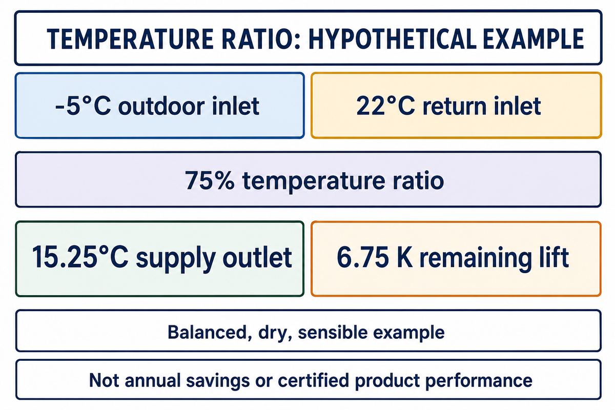
When measured on the supply side, the temperature ratio is the change in temperature across the recovery section compared to the available inlet temperature difference. It can be a useful diagnostic tool in a controlled situation. This ratio, however, can’t describe latent recovery, assess the annual amount of energy savings, or distinguish recovery performance if the temperature sensors also pick up heat from the fan or coil.
How to calculate heat recovery efficiency?
For example, consider a balanced, dry, and sensible exchanger. Divide the supply-side air temperature rise through the core by the difference of the return air and outdoor air inlet temperatures. Multiply by 100 to express the result in percentage. Use the temperature measurements at the boundaries of the recovery section, assuming no heating coil in between, and be mindful of operating mode prior to interpreting the results.
Temperature ratio = (Tsupply,out − Toutdoor,in) / (Treturn,in − Toutdoor,in).
With an outdoor air temperature of -5°C and a return air of 22°C and an assumed ratio of 0.75, the temperature of the leaving supply air would be -5 + 0.75 × 27 = 15.25°C. The remaining lift to 22°C is 6.75 K. These are example values and not actual results from a Koven Air test.
Measure the recovery section
- Locate both inlet sensors and the supply outlet sensor at the core boundaries.
- Record airflow on both paths and confirm stable operation.
- Record bypass position, frost mode and any active upstream heating.
- Calculate the temperature ratio and label it with the conditions.
- Compare with a matching selection point, not a maximum catalogue number.
To calculate the effectiveness on this temperature basis, use the site’s temperature efficiency calculator along with the formula, and check the input definitions against measured locations. For unequal flows, the proper treatment for heat capacity rate should be used. With an inlet difference of almost 0 K, the denominator isn’t useful for a reliable percentage; uncertainty in the sensor could be the greatest source of error. An outlet reading downstream of a running fan isn’t the core outlet air temperature.
Engineering note: Apply the sensor locations and uncertainty treatment required by the chosen method, such as ASHRAE 84. Specify sensor accuracy in the test plan; this example doesn’t prescribe a universal temperature tolerance.
For the −5°C and 22°C example, a 75% temperature ratio yields 15.25°C before any downstream heating. A proposed 22°C supply setpoint still needs a 6.75 K lift. That distinction lets the designer size the remaining duty without presenting an exchanger percentage as a whole-building energy saving.
Which Test Conditions Must Match Before Comparing Ratings?
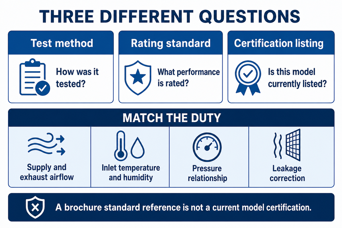
Examine the rated object, supply and exhaust airflow, inlet air temperature and humidity, pressure relationship, and leakage correction. Determine the test method and rating scheme. Just because a standard is mentioned on a brochure doesn’t mean a model within that brochure holds a current certification or that the complete air handling unit has been rated.
ASHRAE Standard 84-2024 focuses on testing air-to-air heat and energy exchangers. The public AHRI 1060/1061 scope provides performance rating coverage for components and packaged equipment, excluding runaround loops. A test method, a rating standard and a certification listing each provide a separate answer.
The AHRI guide to air-to-air energy recovery ventilators states that annual operation shouldn’t be predicted with a single-point method.
“nor does it provide a means of estimating annual energy use.”
Ask for the model and listing, followed by selected-duty data. EATR and OACF pertain to air transfer and airflow correction. Neither is a synonym for heat exchange efficiency. Fan certification, an approved-make list or component certificate shouldn’t be provided as recovery certification for the complete HVAC system.
A specification at 8,000 m³/h should include results at that stated duty, with the exhaust flow and pressure relationship defined. A higher percentage from a lower flow catalogue point won’t settle the comparison. If a supplier can’t provide conditions matched to the specification, treat the offer as technically unresolved and don’t accept the headline rating as verified equivalence.
Why Heat Exchanger Type Changes the Rating
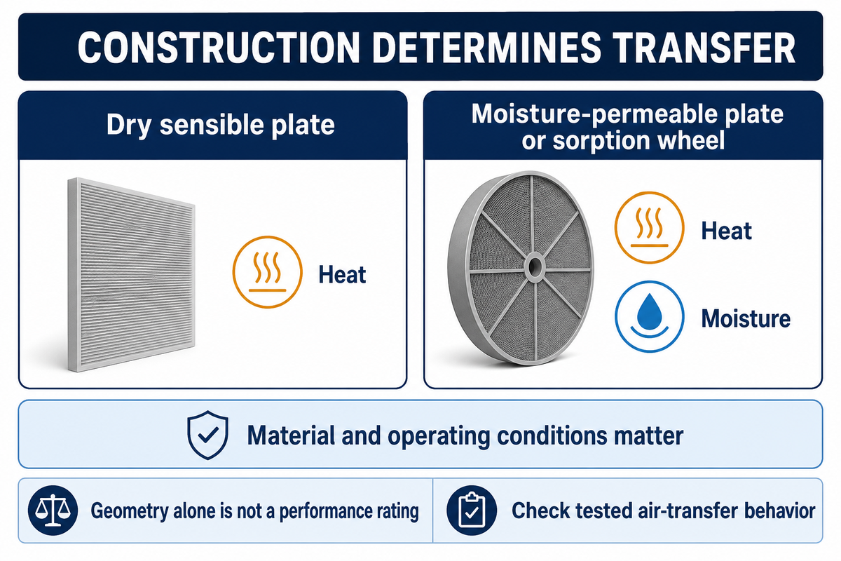
Heat exchanger technology determines which properties pass between the air streams. Sensible plate heat exchangers predominantly exchange heat, while moisture can also be transferred by the use of a membrane plate or a sorption wheel. Cross flow, counter flow and rotary arrangements describe geometry and operation, and don’t supply a complete performance rating.
The AHRI exchanger guidance differentiates sensible and enthalpy devices. Ask which transfer mechanism is applicable to the construction offered.
Heat is transferred to the cooler air stream by a temperature difference. In an enthalpy wheel, the rotating wheel also uses its moisture transfer surface, if there’s any. A thermal wheel label alone doesn’t signify latent recovery. Ask what the wheel transfers and request a material-specific selection.
| Type or operating case | Useful comparison | Missing item that changes the decision |
|---|---|---|
| Dry sensible plate | Sensible effectiveness | Pressure loss at specified flow |
| Moisture-permeable plate | Sensible and latent recovery | Membrane properties and operating conditions |
| Sensible rotary exchanger | Temperature-related recovery | Drive input and transfer characteristics |
| Sorption-treated enthalpy wheel | Separate sensible and latent ratings | Coating, purge arrangement and pressure relation |
| Cross-flow arrangement | Matched selection point | Core construction and pressure loss |
| Counter-flow arrangement | Matched selection point | Installed space and pressure loss |
| Cold duty with frost protection | Mode-dependent net recovery | Preheat, reduced flow or defrost sequence |
| Unequal supply and exhaust flows | Defined capacity-rate calculation | Mass flows and rating denominator |
| Economizer or bypass operation | Ventilation load with recovery disabled | Damper position and control trigger |
| Humid cooling duty | Total and latent load remaining | Humidity ratios and downstream coil duty |
Selection limit: a plate or wheel label doesn’t guarantee zero leakage or unacceptable transfer, respectively. The project’s contamination constraints and the tested air-transfer behavior must govern. For a larger selection of hardware, access and maintenance, refer to the separate equipment selection and maintenance guide.
What Can Make a Good Laboratory Rating Misleading?
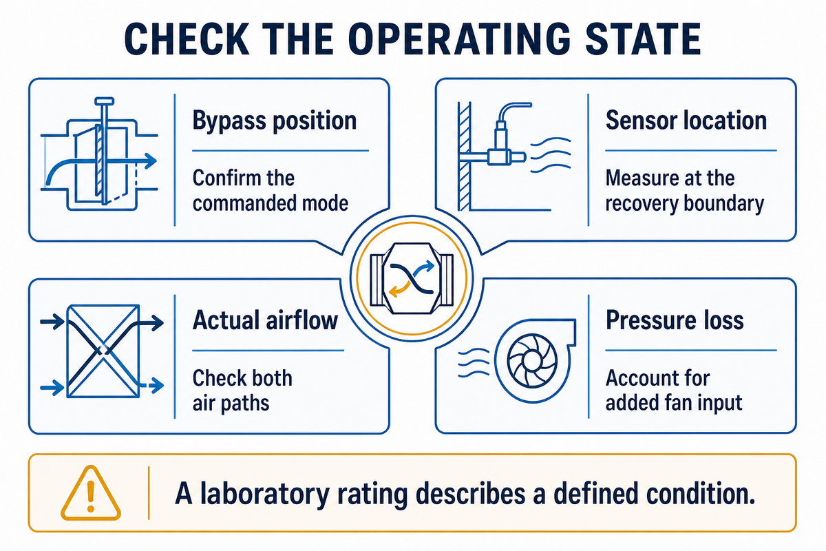
Energy consumption and other problems can affect heat recovery performance in the field. A laboratory rating describes a defined condition. As such, further analysis may require operating parameters and control states, especially when quoted recovery percentage remains high while energy consumption or the remaining coil load increases.
What are the downsides of using a heat recovery system?
A heat recovery system typically adds equipment, air path resistance and increased maintenance, and certain operating modes reduce recovery. By itself, moisture transfer doesn’t directly control room humidity. The real limitations depend on the core and the way it’s installed, so assess net energy, air transfer restrictions and the operating sequence among other things, compared to the stated efficiency.
The HVI rating definitions give reasons why electrical usage, airflow imbalance and defrost corrections are included in the residential rating scheme. For a commercial offer, inquire about the operating allowances associated with its stated method.
Advantages
Recovery can reduce the ventilation load and the remaining heating or cooling duty.
Limitations
Pressure loss, auxiliaries and unsuitable recovery modes can reduce or reverse that energy benefit.
Hidden-bottleneck map: higher recovery-section pressure loss points to fan electrical demand; frost protection points to auxiliary heating and interrupted recovery; an unexpected supply temperature points to bypass position and sensor location. Poor ventilation performance also calls for checking actual air flow rates. Increasing heat recovery effectiveness can’t correct an undersupplied building by itself. Recovering heat can reduce the energy needed for air conditioning, but can’t replace the missing air quantity.
Hypothetical Commissioning Scenario: A facilities team observes a low supply temperature on a cold morning. The first suspect is a defective heating coil. The logged position of the recovery damper shows an open bypass under economizer command. The controls engineer determines the building isn’t requesting free cooling, examines the controls sequence and adjusts the command if required. If the bypass is conflicting with the requested command, the conflicting controls command should be corrected and the command rechecked. Use controls sequence tests to check whether the controls are functioning as designed. In the absence of the controls test results, the owner requests a witnessed sequence test before accepting the built-in controls.
At an assumed flow of 2 m³/s per path, an additional 150 Pa pressure loss on each path would require an additional 1.00 kW of fan input when total fan efficiency is 0.60. A pressure reading should be taken with the recovery temperature measurement. The same percentage may have a different operating cost if the air path resistance changes.
When Does Higher Effectiveness Stop Saving Energy?
Purchased-energy savings continue to increase until the extra fan and auxiliary input equals the added useful recovery expressed as avoided equipment input. Subtract electrical penalties after converting recovered thermal energy to avoided equipment input. Heating equipment determines the conversion. Additional energy for auxiliaries also counts, and active demand must make use of heat recovered by the core.
A 2015 National Institute of Standards and Technology study found added HRV fan energy offset savings from heat pumps in the case study of a single-family residential application. While the study may not predict a commercial building’s savings, it demonstrates the importance of “heat recovered” and “electricity avoided” being kept separate.
Matched-duty net-energy comparison
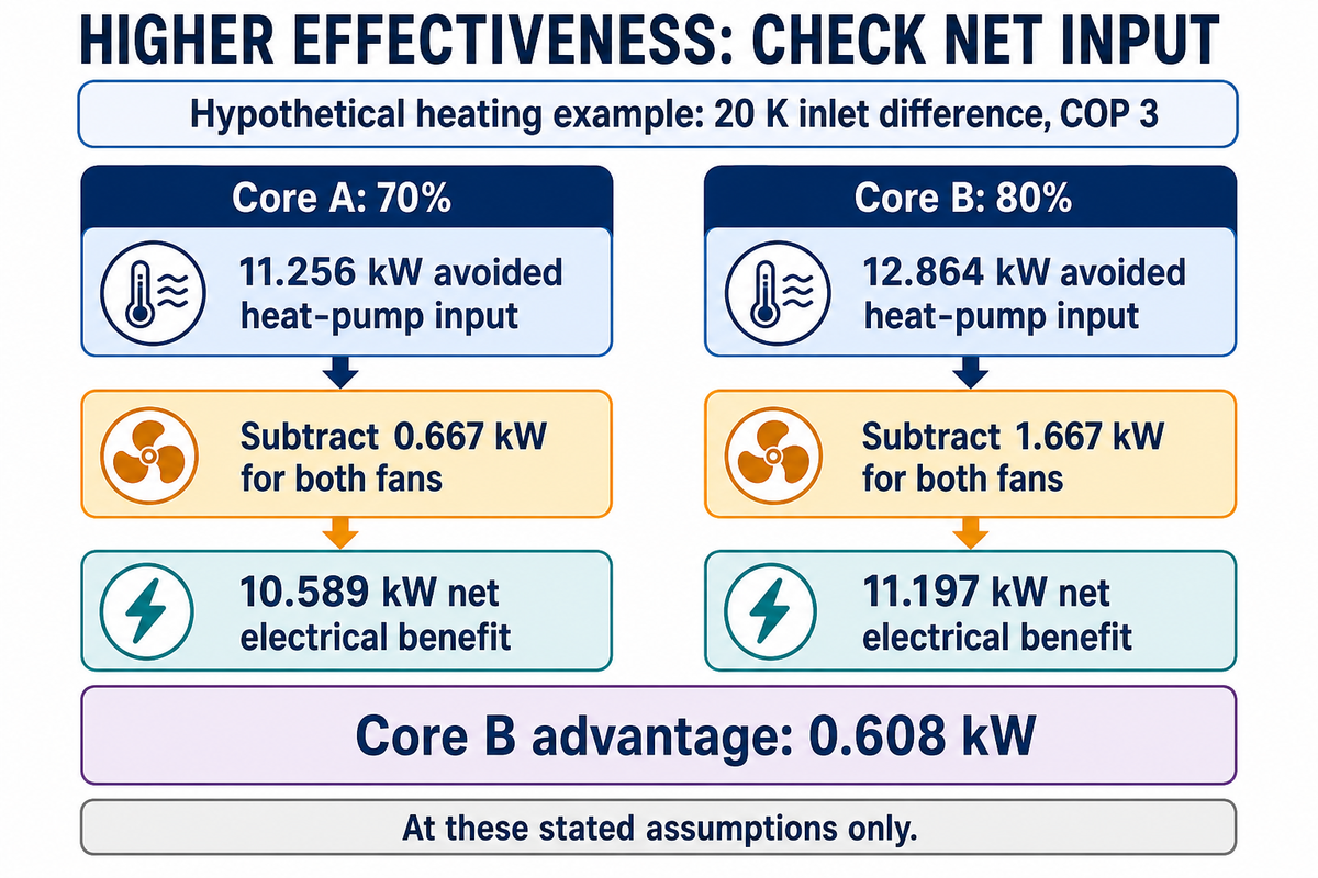
Hypothetical heating scenario: Let’s consider a hypothetical heating example with two dry sensible cores, where each core serves 2 m³/s of air flow per air path. Assume air density 1.2 kg/m³, specific heat 1.005 kJ/(kg·K), a 20 K inlet temperature difference and heat-pump heating COP 3. Assume the heat pumps serving both cores have a heating COP of 3. Core A has 70% effectiveness and 100 Pa recovery pressure loss per air path; Core B has 80% effectiveness and 250 Pa per air path. Each fan has a wire-to-air efficiency of 0.60. All inputs presented are hypothetical. Both systems have enough heating demand to use all heat recovered. For this example, latent transfer, frost control, and other auxiliaries have been neglected; for a complete real world comparison, the input of wheel motors and other auxiliaries would also have to be considered.
Sensible power recovered is ρ × cp × airflow × temperature difference × core effectiveness. Added fan input for each air path is airflow × recovery pressure loss / (total fan efficiency × 1,000) in kW. This is in line with the flow, pressure and efficiency relationship explained in Scott Smith’s Minimizing Fan Energy and the total efficiency here includes motor and drive losses.
| Quantity | Core A | Core B |
|---|---|---|
| Core sensible effectiveness | 70% | 80% |
| Recovered thermal power | 33.768 kW | 38.592 kW |
| Avoided heat-pump input at COP 3 | 11.256 kW | 12.864 kW |
| Both fans’ recovery-related input | 0.667 kW | 1.667 kW |
| Net electrical benefit | 10.589 kW | 11.197 kW |
Core B gains 4.824 kW of thermal recovery but only 0.608 kW of net electrical benefit after the heat-pump conversion and extra fan input. Under these fixed assumptions, the break-even inlet temperature difference is about 12.44 K. At 10 K, Core A provides about 0.196 kW more net benefit. Below the heating-demand range, the model no longer describes the control decision.
Finance check: Don’t insert an SRE value (already adjusted for fan energy) into this calculation and subtract fans again. Nor should either net value be multiplied by a full year’s hours. Weather bins, schedules, part-load equipment performance and bypass modes determine the annual result. A boiler-based comparison also requires fuel input and cost to be separated from fan electricity.
In a 10-percentage-point improvement of Core B in the assumed 2 m³/s system, an additional 0.608 kW of electrical benefit is realized at 20 K. The same advantage disappears near 12.44 K. A higher purchase price requires a weather based annual calculation to determine finance’s payback evaluation.
From a Published Model Table to a Comparable AHU Quotation
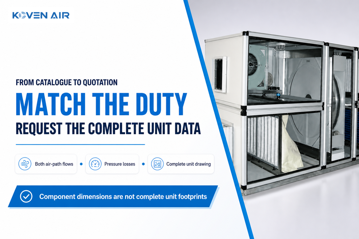
We recognize some published model tables establish an initial airflow and space reference, but we require comparable data for selected-duty performance. Maintain each dimension to its respective physical object. Recovery section, fan section and wheel dimensions can’t be taken as complete unit footprints, even if their listed airflows match.
According to Koven Air’s published heat recovery AHU configurations, plate model 0815 is listed at 8,000 m³/h, with a 1,600 mm recovery section and a 900 mm fan section. Its separate wheel table lists a 1,400 mm wheel at 3 m/s and 8,000 m³/h. These figures describe various geometries, and do not represent complete casing dimensions, certified recovery efficiency or net savings of either selection.
Catalogue-to-quotation gap map
| Parameter | Recommended range | Why it matters | How to verify |
|---|---|---|---|
| Supply and exhaust duty | Project design flows in m³/h | Sets comparable duty | Selection sheet for both paths |
| Inlet conditions | Project design °C and humidity values | Sets sensible and latent opportunity | Matched heating and cooling points |
| Core recovery | Required sensible and latent performance | Defines useful transfer | Named method and model evidence |
| Pressure loss | Project pressure budget in Pa | Changes electrical demand | Both recovery paths at selected flow |
| Fan and auxiliary input | Selected-duty input in kW | Completes net comparison | Motor, drive and auxiliary schedule |
| Installed space | Available dimensions in mm | Includes access and service removal | Complete general arrangement drawing |
| Control modes | Occupied, bypass and frost sequence | Determines usable recovery hours | Written sequence and commissioning test |
Buyer objection: “Both options provide a flow of 8,000 m³/h, so why request more information?” The flow is one of many factors to be specified. The supplier has to provide the same set of information on both options and keep the equipment supply separate from the installation using a quotation scope comparison.
The published 1,600 mm recovery section and 1,400 mm wheel diameter can’t determine which AHU is smaller. At their listed 8,000 m³/h, request general arrangement drawings and performance sheets. This would allow procurement to perform a defined recovery solution comparison without estimating dimensions or efficiencies.
Industry Outlook: Operating Conditions Matter More Than Market Share
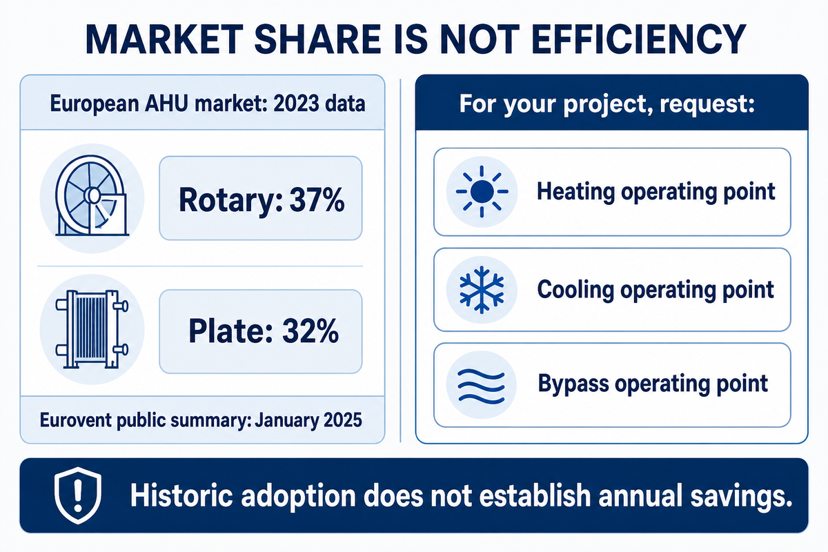
Demand specifications for future work should request performance and control information for various operating conditions and not just one maximum efficiency. Recovery bypass control has recently been the subject of published research, and there’s market data illustrating recent equipment trends. Neither a popular exchanger type nor a recent piece of research validates that one control strategy or one equipment type offers the best potential annual savings for a given installation.
A September 2026 NIST publication by Andrew Shore and Yunho Hwang compares free-cooling strategies in a residential model across 15 U.S. cities. It uses temperature- and enthalpy-based bypass, and looks at added heat from recovery during cooling. Its results support checking the controls question; they aren’t commercial AHU saving percentages or proof that one bypass strategy wins everywhere.
Eurovent Market Intelligence’s January 2025 public summary states that rotary exchangers made up 37% of the European AHU market, while plate exchangers made up 32%, in its 2023 data. Those figures represent historical market shares and aren’t thermal efficiencies or a forecast for 2026. Residential MVHR data shouldn’t be used to proxy commercial AHU market demand.
Better energy performance means a useful decrease in purchased energy for the owner. Comparing environmental impact and primary energy requires the relevant energy factors as well. A vendor providing “energy efficient” heat recovery units should provide the mode-specific data necessary to test that claim and provide what happens to the incoming air in summer.
Takeaway for the next specification
Match the rating first. Model the purchased energy second. For an 8,000 m³/h request, ask for heating, cooling and bypass operating points, both air-path pressure losses, and a complete unit drawing. Keep historic market shares out of the efficiency calculation.
Frequently Asked Questions
Heat recovery questions address the performance of exchangers and ventilation in the same breath. Answers to questions in this section remain separate. Commercial decisions involve the use of specified equipment and the airflows and operating sequences. Residential rules of thumb can’t be used to determine the performance of a large-scale building.
What is a heat recovery ventilation system?
It exchanges ventilation air while recovering part of the available energy.
Heat recovery ventilators exchange indoor and outdoor air while transferring some energy between the separate incoming and outgoing ventilation streams. A sensible core mainly transfers heat; an energy recovery core can also transfer moisture. The recovery section reduces part of the ventilation load, but fans, controls and any heating or cooling equipment still consume energy.
Do you need a dehumidifier if you have an ERV system?
Additional humidity control may still be necessary.
You may still need dehumidification because an energy recovery ventilator doesn’t independently maintain the indoor humidity setpoint. Moisture transfer depends on the core, airflow and humidity difference between the incoming and exhaust air. Compare the remaining outdoor air moisture load with the capacity of the cooling coil or dedicated dehumidifier at the actual operating conditions.
Should an ERV run constantly?
Use the building’s ventilation requirements and approved control sequence.
Operating hours should follow the building ventilation requirement rather than a universal always-on rule. Occupancy, outdoor conditions, humidity and exhaust needs can all affect operation. Recovery may be bypassed when it provides no benefit, while mechanical ventilation continues. Ask the designer to document occupied, unoccupied, frost protection and economizer modes for your project, including any permitted role for natural ventilation.
Can heat pumps be 300% efficient?
A heating COP of three describes delivered heat relative to input energy.
A heat pump with a heating coefficient of performance of three supplies three units of heat per unit of input energy under stated conditions. That ratio includes transferred environmental heat. It’s a different measure from passive heat exchanger effectiveness.
How much is a heat recovery ventilation system?
The price requires a defined equipment and installation scope.
An installed price can’t be inferred from the recovery percentage alone. Ask for a quotation that identifies airflow, core type, casing, fans, filtration, controls, frost protection and installation scope. Separate equipment supply from ductwork, electrical work, commissioning and maintenance access. For comparisons, hold those items and the design conditions constant. Residential package prices don’t establish the cost of a commercial air handling installation, and a higher quoted efficiency doesn’t by itself establish a shorter payback period.
Can heat recovery efficiency be negative?
A negative calculated temperature ratio needs investigation of measurements and mode.
A calculated temperature ratio can be negative when the measured temperature change has the opposite sign to the reference difference. Check sensor locations, operating mode and the size of that difference before interpreting it as failed heat recovery performance.
Does heat recovery efficiency increase with temperature?
More recovered heat does not necessarily mean a higher effectiveness percentage.
A larger temperature difference can increase recovered heat without increasing the effectiveness percentage. For a simple sensible example, recovered thermal power depends on airflow, heat capacity, the inlet temperature difference and effectiveness. The core rating can also change with flow, moisture transfer, condensation or frost protection, so it shouldn’t be assumed constant across every condition. Compare tested operating points and distinguish kilowatts recovered from the percentage used to describe the exchanger; the two quantities answer different questions.
Sending a selection request? Include the airflows in each path, design temperatures and humidity, available space and control requirements to justify your request for commercial air handling units. Compare sensible, latent and electrical data before determining a recovery percentage or estimating payback.
Scope and calculation note: Updated October 2026. This article compares air-to-air ventilation recovery metrics. Worked examples use stated hypothetical inputs and aren’t certified Koven Air performance or field tests. Manufacturer dimensions are attributed to the public catalogue. Project-specific savings require an appropriate design and operating model.
References & Sources
- HVAC Energy Recovery Ventilation, U.S. Department of Energy.
- Ventilation A to Z, Home Ventilating Institute.
- New Metric Available for HRV and ERV Performance, Home Ventilating Institute.
- Titles, Purposes and Scopes, ASHRAE, Standard 84-2024 entry.
- AHRI 1060 and 1061 performance rating scope, Air-Conditioning, Heating, and Refrigeration Institute.
- Air-to-Air Energy Recovery Ventilators, Air-Conditioning, Heating, and Refrigeration Institute.
- Energy Use Consequences of Ventilating a Net-Zero Energy House, National Institute of Standards and Technology, 2015.
- Minimizing Fan Energy, Scott Smith, HPAC Engineering, 2012.
- Energy Recovery Ventilator Free Cooling Strategies Across the U.S., National Institute of Standards and Technology, 2026.
- HVACR 2030 report by Eurovent Market Intelligence, public summary, January 2025.