
Get in Touch with Koven Air Company

Updated September 2026
Desiccant dehumidifiers are air-treatment systems that remove water vapor by transferring it to a moisture-attracting material, then regenerating that material so the cycle can continue. These systems are especially useful when air is cold, dew-point requirements are low, or a process needs stable moisture rather than comfort control. Here, the focus is physics, measurements and operating evidence; product sizing and model selection remain on the solution page.
Guide at a glance
- “Desiccant” describes a family of systems, not one universal machine design.
- Relative humidity is a function of temperature. For a direct comparison of moisture state, use dew point or humidity ratio.
- Heat-regenerated rotors typically use separate process and reactivation air streams.
- Performance cannot be assessed from outlet-air dryness alone. Both air paths and air flows must be measured.
- Information on the capacity and configurations of desiccant dehumidifiers as well as on business solutions can be found on the Desiccant Dehumidifier Solutions Page.
What Is a Desiccant Dehumidifier, and How Does It Work?
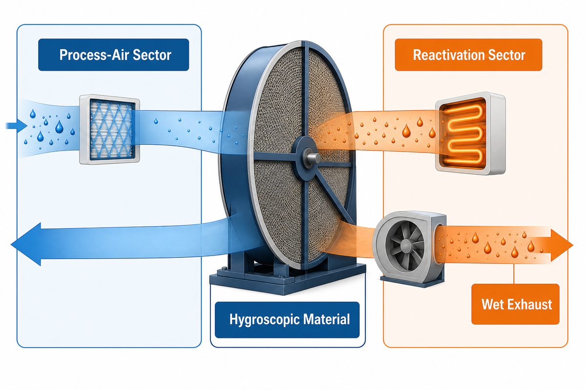
Desiccant dehumidifiers are air-treatment systems that transfer water vapor from an air stream to a hygroscopic material. In a solid desiccant system, vapor is adsorbed on the surface of the material. In a liquid desiccant system, water is absorbed into a concentrated solution. The desiccant must be regenerated by the application of heat, a pressure change or another driving force consistent with the system.
That distinction matters. The familiar industrial rotary unit is only one member of the family. Its honeycomb rotor turns between a process-air sector and a heated reactivation sector. Moisture moves from process air onto the rotor. From there, it moves into the reactivation air and leaves through a wet exhaust. Liquid systems circulate a solution between contacting and regeneration sections. Pressure-regenerated compressed-air dryers operate under a different pressure and purity framework. These architectures should not all be called heated wheels. Doing so hides the measurement boundary an engineer actually needs.
The common principle is a vapor-pressure difference. The desiccant presents a lower water-vapor potential than the incoming air, so vapor moves toward it. Regeneration reverses that driving force. Dry air is often warmer because adsorption releases heat, and the equipment may carry some regeneration heat across its internal boundary. If a process needs a lower supply temperature, downstream cooling belongs to the full system even though it is not the moisture-removal mechanism.
Put plainly, humid air meets a drier desiccant material. Moisture is adsorbed by a solid surface or absorbed into a liquid. Regeneration then moves that water to another stream. Moisture transfer depends on the inlet state, flow, sorbent condition and regeneration driving force. Desiccant formulations and equipment construction vary. Material selection and condition both affect moisture removal.
Evidence boundary: the cited U.S. Department of Energy laboratory report treats performance as application-specific because airflow and regeneration conditions define the test boundary. The risk is transferring one tested result to a different architecture.
Language check
The collection of molecules on surfaces is termed adsorption. Absorption refers to the movement of molecules into the volume of a liquid or material. Solid rotors are generally treated as adsorption systems. Liquid desiccants are generally treated as absorption systems.
Relative Humidity vs. Dew Point: Which Number Actually Describes Dryness?
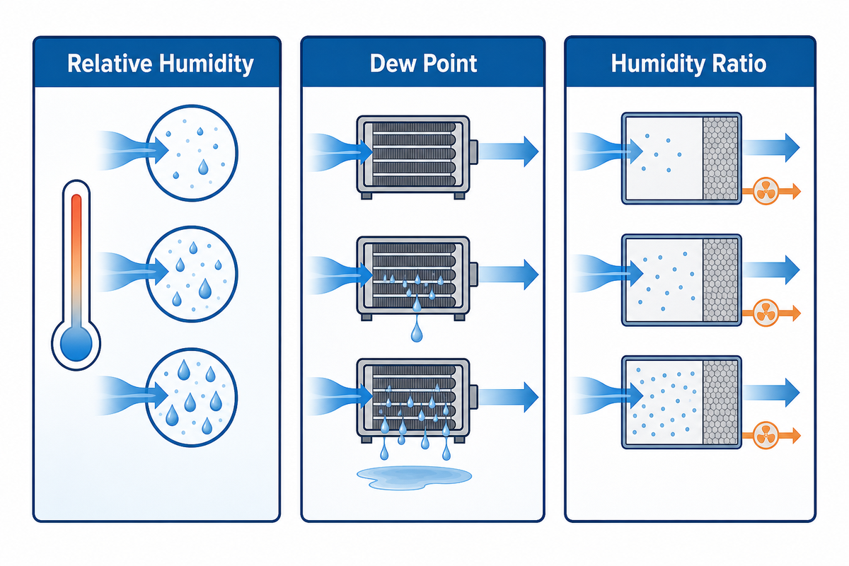
Relative humidity (RH) shows how close air is to saturation at its current temperature. Change the temperature without adding or removing water, and RH changes. Dew point is the temperature at which that air becomes saturated when cooled at the stated pressure. It is a more stable way to discuss the moisture condition of room or process air. Humidity ratio is useful for load calculations because it represents the mass of water vapor relative to dry air.
| Measurement | What it tells you | Main caution |
|---|---|---|
| Relative humidity | Proximity to saturation at the current temperature | Changes when temperature changes |
| Dew point | Condensation threshold and moisture state at a stated pressure | The pressure reference must be clear |
| Humidity ratio | Mass of vapor per mass of dry air | Requires consistent units and state inputs |
RH alone can mislead. Heated air generally shows a lower RH even when no moisture has been removed. Dew point and humidity ratio reveal whether water-vapor content changed. Warm air leaving a desiccant rotor can therefore have a low RH. A lower outlet dew point is the stronger evidence of actual drying.
Logs labeled only “humidity levels” are incomplete. Record temperature and humidity together, then retain the calculated dew point or humidity ratio. Those values show whether water vapor in the air actually changed or whether the air merely became warmer or colder.
Measurement evidence: the cited Federal Register test-procedure discussion treats sensor placement and moisture measurement as part of the test method because an unreferenced RH reading creates a verification risk.
The Moisture-State Ladder
- State the temperature and pressure reference.
- Record RH plus dew point or humidity ratio.
- Describe the actual moisture load contributed by ventilation, infiltration, people, products, and processes.
- Set the control target at the relevant location and operating state.
Atmospheric dew point for a room is not interchangeable with pressure dew point for compressed air. Compressing air changes water-vapor partial pressure; a compressed-air specification is incomplete unless the pressure reference is stated. Pressure-regenerated dryers also sit within a broader compressed-air purity framework such as ISO 8573. This article focuses on atmospheric HVAC and process-air dehumidification, so compressed-air dryer selection and diagnosis are outside its core scope.
Follow the Moisture Through the Two Airstreams
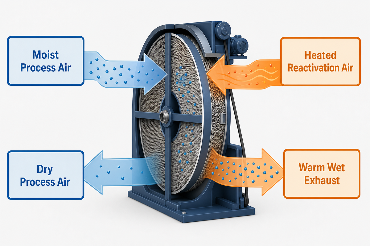
For a common heat-regenerated rotary dehumidifier, follow the water molecule rather than the component list. Process air enters one sector of the rotor. The dry desiccant surface attracts vapor, and drier, usually warmer, process air leaves for the controlled space or downstream treatment. As the rotor turns, its moisture-loaded section enters the reactivation sector. Heated air releases the vapor from the desiccant and carries it out as warm, wet exhaust.
The 2-Airstream Moisture Map
Moist process air
known inlet state + flow
known inlet state + flow
→
Dry process air
verified outlet state
verified outlet state
water vapor transfers through the rotating desiccant medium
Heated reactivation air
known inlet state + flow
known inlet state + flow
→
Warm wet exhaust
moisture exits the system
moisture exits the system
This map shows two design consequences. First, reactivation exhaust is part of the moisture-removal path. Poor routing can recirculate removed moisture near the process intake. Second, both air paths must remain balanced. Heater temperature, rotor speed or outlet dew point without airflow context is only a partial observation.
System evidence: the Department of Energy laboratory report measures both airstreams because a drying claim without flow and regeneration context creates a mass-balance gap.
The map isn’t all-inclusive. Liquid-desiccant loops transfer moisture to a solution, move that solution, and regenerate it in a separate contactor. Pressure-regenerated compressed-air dryers may use purge air or a pressure swing instead of a hot reactivation section. The measurement plan should be based on the actual dehumidifier design installed.
A Map of Desiccant System Types
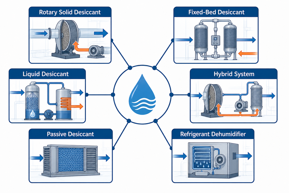
| System type | Moisture mechanism | Useful boundary |
|---|---|---|
| Heat-regenerated rotary solid desiccant | Adsorption on a rotating medium; thermal regeneration | Continuous atmospheric process air; see the rotary guide |
| Fixed-bed solid desiccant | Adsorption in vessels or beds that alternate between drying and regeneration | Cyclic atmospheric-air duties where switching behavior is acceptable |
| Liquid desiccant | Absorption into a concentrated solution; solution regeneration | Latent-load treatment and liquid circulation; see the liquid guide |
| Hybrid desiccant and refrigerant | Desiccant manages latent load while coils manage sensible load | Integrated systems where neither component should be assessed alone |
| Passive chemical desiccant | Finite moisture uptake in a replaceable or regenerated pack | Small enclosures and packaging, not continuous industrial airflow duty |
| Refrigerant dehumidifier | Cooling below dew point and condensing liquid water | Warm, moderate-RH duty; see the commercial comparison guide |
| Heatless compressed-air dryer | Adsorption with pressure swing and dry purge air | Adjacent compressed-air class; pressure dew point must be stated |
| Heated compressed-air dryer | Adsorption with heat-assisted regeneration and purge variants | Adjacent class with compressor and purge energy boundary |
| Membrane compressed-air dryer | Selective vapor permeation rather than a regenerated desiccant bed | Useful comparison boundary; not a desiccant architecture |
Classification evidence: the U.S. Department of Energy laboratory report shows why an architecture label is not enough: application conditions and regeneration method must be stated because otherwise a comparison risks a category mismatch.
When Desiccant Dehumidification Is the Right Fit
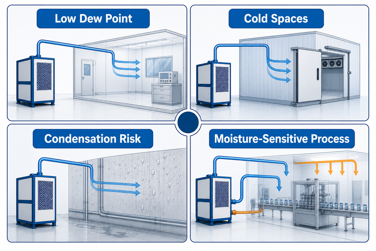
Desiccant technology becomes worth considering when the control problem is difficult for a cold coil. Typical signals include a low required dew point, operation in cold spaces, condensation risk on cold products or surfaces, and a process where moisture variation affects yield, storage stability or corrosion. It can also handle ventilation latent loads separately from sensible cooling when a dedicated outdoor-air strategy benefits from that separation.
This doesn’t necessarily mean that using a desiccant system is always the best option. In a situation with a warm space and a moderate comfort target, a refrigerant system can be used to remove moisture with a simpler design and without the need for exhaust ducts. A desiccant system justifies the additional path of air, the controls, and the load of regeneration when such a design is warranted.
A defensible early decision is based on conditions and not room names. Consider the most credible worst possible outdoor and process air conditions, the controlled space temperature, desired dew point, infiltration and ventilation, product moisture release, the operating schedule, and the available utilities. These define the need for a desiccant system, and then the model selected and the configuration of the rotor should be addressed in the review of the desiccant dehumidifier range.
Cold storage is a useful example. Opening a door lets outside air in. When that air reaches cold surfaces, its moisture may condense or freeze. The engineering question is not simply the room’s percentage RH. Ask whether moisture state, door cycles and infiltration volume will cross a critical surface temperature. In pharmaceutical, food or materials processes, the trigger may instead be product equilibrium, coating behavior, microbial risk or corrosion. The same equipment category can serve these applications, but the control target and evidence of success differ.
Cold temperature can also affect the practical technology choice. A refrigeration coil near freezing may need a defrost cycle, reducing effective moisture-removal time. Adsorption does not require vapor to condense on the process side. That does not make every cold operation a desiccant application. The inlet state, target and total system boundary remain decisive.
Facilities where ventilation dominates present another boundary condition. Even when the internal load of moisture is low, the latent load can be dominated by outdoor air. The moisture can be removed from the air prior to it reaching the space to be controlled, while separate cooling equipment manages the air temperature. This approach can be effective, but only when fan systems, regeneration, and cooling are considered as an integrated system. A comparison of components may favor one system over the other when the desiccant’s system boundary isn’t defined.
Where the Energy Goes Depends on the Regeneration Architecture
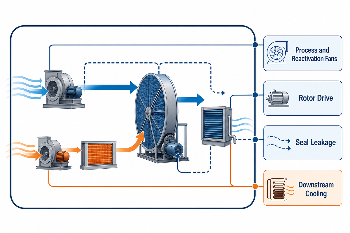
The visible heater is one part of a heat-regenerated rotary system, but it is not the entire energy boundary. The system may include process and reactivation fans, controls, rotor drive, cooling and pressure losses through filters, seals and ductwork. Water vapor, not process air, is adsorbed. Sorption heat can warm the air. Internal heat carryover can raise the outlet temperature. If the dry air must be cooled downstream, that duty belongs in the total operating cost.
Leakage and purge are equally important. Seal leakage can carry moist reactivation air across into the nominally dry process path. Excess reactivation airflow can increase fan and heating duty, while insufficient flow can fail to carry released moisture away. Heat-recovery value depends on temperature levels, contamination risk, pressure balance, schedule and control strategy. A single regeneration temperature or universal efficiency figure cannot describe all of these conditions.
Energy evidence: the Department of Energy laboratory report evaluates a defined application because heater input, fan flow, leakage and downstream cooling can shift the apparent result. Ignoring one boundary creates a comparison risk.
Other architectures shift the energy boundary. One example is a pressure-regenerated compressed-air dryer which may choose to use some compressed purge air, making the compressor-side penalty material. Another example is a liquid-desiccant system which requires additional pumps, solution concentration and regeneration, and in some configurations can be linked with low-grade heat. Electrically driven regeneration or heat-pump integration can alter the point where the system absorbs energy, but in no way eliminates the need to specify the energy boundary.
Trend these instead of chasing one headline number
- Process inlet and outlet temperatures, dew point and humidity ratio, and airflow.
- Reactivation inlet and exhaust state, airflow and heater input
- Pressure drop across the filter and rotor, seal leakage and rotor speed.
- Downstream cooling duty and any recovered-heat contribution
- Outputs for each operating mode, in addition to a total monthly utility consumption.
Troubleshooting by Symptom, Not by Guesswork
Scope: this main diagnostic table is for heat-regenerated rotary equipment used to treat atmospheric process air. It’s a measurement sequence and isn’t a replacement of the manufacturer’s electrical, burner, steam, gas or high-temperature safety instructions.
The 4-State Diagnostic Framework
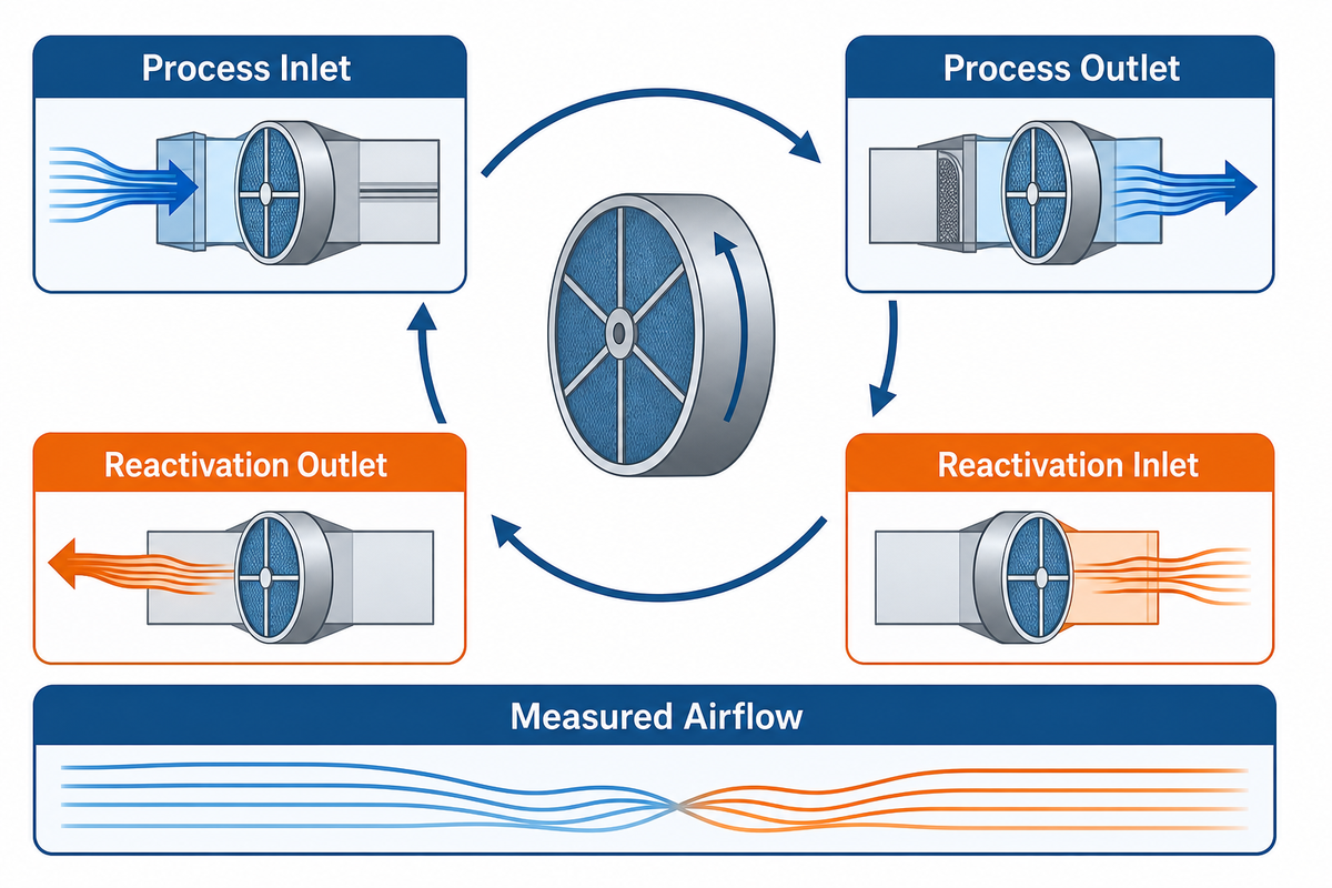
The Four-State Diagnostic Loop is the most valuable discipline. In a single, stable operating mode, measure the process inlet and outlet, reactivation inlet and reactivation outlet. Couple those four states, along with measured airflow (or at least a reasonable approximation, such as fan speed and pressure and damper position) in both directions. Without airflow, a change in temperature or dew point can’t be made into a performance assessment.
| Symptom | Check the evidence | Safe next step |
|---|---|---|
| Weak drying | Both inlet/outlet moisture states; both airflows; filters; rotor rotation; seals; reactivation heat | Correct proven airflow or component faults; do not simply raise heat |
| Unstable outlet dew point | Load swings, bypass leakage, control sequence, sensor location, sensor response and stratification | Stabilize the test period and cross-check with a suitable reference instrument |
| Rising pressure drop | Filter differential pressure, rotor face loading, duct obstruction and damper position | Inspect and service within approved procedures before airflow is lost |
| High reactivation temperature but poor drying | Reactivation flow, heat delivery location, rotor speed, seal leakage, contamination and wet-exhaust recirculation | Treat heat as one reading, not proof of regeneration |
| Unexpectedly warm dry air | Sorption heat, carryover, airflow balance and downstream coil state | Verify the design outlet-temperature boundary before altering rotor operation |
Low-humidity measurement requires the same care as other measurements. Sensor accuracy and response can deteriorate near the edge of an instrument’s range. Poorly placed probes may read a horizontal layer of cold or hot air rather than mixed air. Variable atmospheric pressure and air density with altitude change mass flow even when a volume reading appears unchanged. Duct leakage can make machine-inlet data differ from chamber conditions. Record the instrument, location, pressure reference and test state so another engineer can duplicate the measurement.
Sequence matters during a field test. First let the machine and controlled process reach a stable mode. Next confirm that dampers, fans, heater stages and rotor speed match the intended sequence. Then record the four air states and flow evidence at close timestamps. Compare process-side moisture transfer with the rise on the reactivation side. A large unexplained imbalance points toward leakage, sampling error, unstable load or a missing boundary. This order is more informative than changing several setpoints at once and watching only room RH.
Diagnostic evidence: the cited Federal Register measurement discussion highlights sensing method and placement because an unstable or poorly referenced reading creates a verification risk.
Safety interlocks shouldn’t be disabled to conduct a diagnostic test. Airflow is critical to dissipate heat in order to protect system components from excessive temperatures. Many sites install extra site-specific safeguards for fuel-fired or steam regeneration. If the test requires reaching and operating energized panels to perform combustion adjustments or work near a hot rotor section, qualified service personnel and equipment approved procedures take precedence over the information contained in this guide.
For liquid-desiccant systems, add evidence pertaining to solution concentration, solution temperature, circulation, carryover, risk of crystallization and material compatibility. For pressure-regenerated compressed air dryers, make use of the manufacturer’s pressure-dew-point and purity diagnostics rather than this atmospheric-air table.
Maintenance and Commissioning Records That Matter
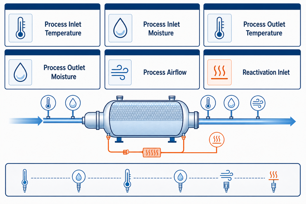
Good commissioning records become the machine’s troubleshooting baseline. Capture process conditions, downstream cooling state and the reactivation inlet and outlet. Record airflow or a validated proxy, filter and rotor pressure drops, rotor speed, damper position, seals, heater state, alarms and control setpoints. Add instrument identity, calibration status, measurement location, operating mode and atmospheric pressure. Numbers without their measurement method are difficult to compare months later.
The 12-Field Commissioning Record
| Field | Record with units |
|---|---|
| Process inlet temperature | °C and, when required, °F |
| Process inlet moisture | % RH, °C dew point and g/kg humidity ratio |
| Process outlet temperature | °C and °F |
| Process outlet moisture | % RH, °C dew point and g/kg humidity ratio |
| Process airflow | m³/h or CFM with Pa or in. w.g. reference |
| Reactivation inlet | °C, % RH and m³/h or CFM |
| Reactivation exhaust | °C, % RH and m³/h or CFM |
| Filter pressure drop | Pa or in. w.g. |
| Rotor pressure drop | Pa or in. w.g. |
| Heater input | kW, kWh over the test or stated steam/gas units |
| Atmospheric reference | kPa or psi absolute, plus site altitude in m or ft |
| Rotor and control state | rpm, Hz, % command and timestamp in h:min:s |
Maintaining routine operation means looking for evidence that deviates from baseline conditions. Filters and seals protect airflow, sorbent surfaces and airstream separation. Rotor inspection identifies contamination or damage. Drive and belt condition confirm that the rotor is moving at the required speed. Heater and airflow interlocks need functional tests, while dew-point sensors need a verification interval suited to the process risk.
Trend logs are most effective when distinguishing operating modes. Startup, normal production, setback, defrost or washdown recovery shouldn’t be averaged together. Record the dates of planned filter changes or sensor calibrations in the trend. After a maintenance action, perform another stable point test and analyze the results in comparison to the commissioning baseline. This provides evidence of restoration of performance, but could also reveal that the original performance issue is still present.
Documentation quality starts before field operation, with 18 standardised production stages providing one example of a traceable manufacturing record. As a first-party example, Koven Air describes 400 traceable manufacturing steps per unit, 36 factory inspections and a 24-hour burn-in. These factory-process statements do not prove a field dew point or service life, but they illustrate the serial inspection and test records a buyer can request and retain.
There is no universal service-life number for a desiccant dehumidifier. Service life depends on operating mode, operating hours, temperature exposure, contamination, filtration, seal wear, drive alignment, maintenance and standby duty. Condition indicators such as outlet dew point, pressure drop, leakage and regeneration state are usually more informative than age alone.
What Are the Disadvantages and Limits?
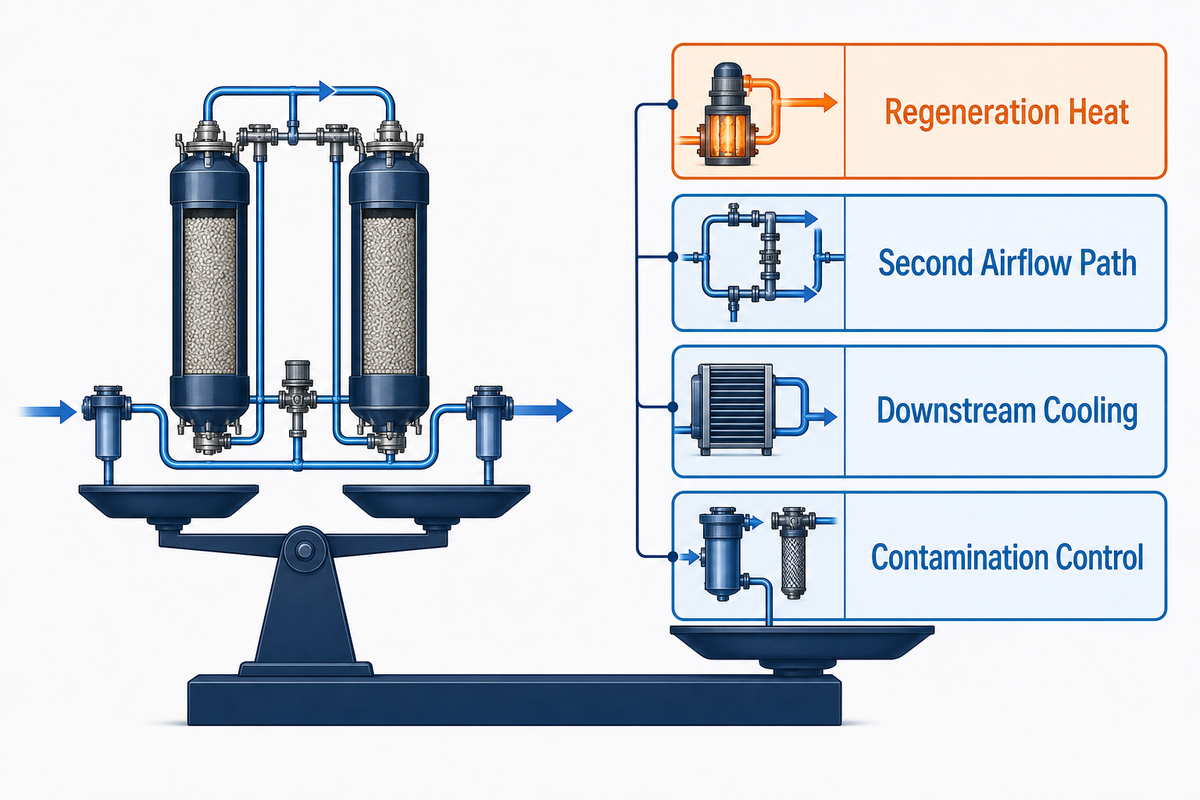
Desiccant dehumidifiers trade low-dew-point capability for system complexity. Thermally regenerated units require a heat source, a reactivation airstream and a safe wet-exhaust route. Process air may leave warmer, increasing downstream cooling demand. Two air paths add fans, filters, dampers, seals, ductwork and controls that must remain balanced.
The sorbent is also sensitive to contamination. Aggressive chemicals, process aerosols, dust and oil may damage components or block sorbent surfaces, so filtration and material compatibility remain concerns when evaluating the application. Controls and sensors must operate in the target moisture range. Standard room instruments may be inadequate in a low-dew-point process. Maintenance should not be reduced to changing a single filter.
The technology can also be unnecessary. When air is warm and the target is moderate, a refrigerant system may be simpler. No arbitrary one-year state should decide that comparison. Instead, examine the regeneration source, removed moisture and exhaust route. Include downstream cooling and control burden in the same boundary.
Comparison evidence: the Department of Energy laboratory report treats energy performance as an application result because operating state and system boundaries change the answer. Component-only comparisons create an overclaim risk.
From General Guide to Engineered Selection
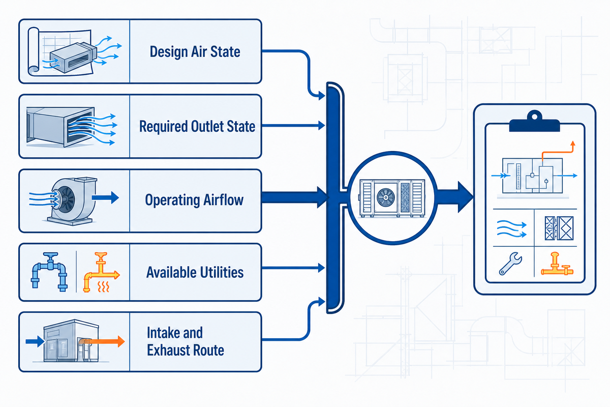
From a general sense, a useful selection process requires the following information:
- Design process-air temperature, dew point, RH and pressure.
- The state of the air at the required outlet and the location where this state is measured.
- Airflow through each operating mode and the ventilation/infiltration assumptions
- Contaminants, product emissions, hygiene or materials-compatibility constraints
- Available electricity, steam, gas, hot water or waste heat
- Acceptable outlet temperature and downstream cooling arrangement
- Reactivation intake and exhaust route, including pressure balance
- Operating schedule, turndown, redundancy, alarms and control integration
- Altitude, ambient extremes and applicable test or documentation requirements
Selection evidence: the U.S. Department of Energy laboratory report treats inlet state, airflow and regeneration conditions as application data because omitting them creates a sizing and verification risk.
This information moves the discussion from general education into application engineering without pretending that one table can size every job. Review available architectures on Koven Air’s desiccant dehumidifier solution page, or send the operating conditions to the engineering team.
What Is Changing in Desiccant Dehumidification?
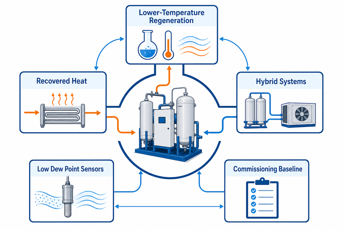
The useful development themes concern the whole-system penalty, not a dramatic standalone moisture number. Research continues into sorbents and configurations that regenerate at lower temperature. Heat pumps and recovered heat can couple drying and regeneration more closely without guaranteeing efficiency in every application. Hybrid systems divide sensible and latent loads between vapor-compression and desiccant stages instead of forcing one technology to do everything.
Even controls are being more evidence based. More reliable low dew point sensors, along with trend logs and an integrated control system for fans, heaters, rotors, and coolers, allow the system to more closely control the actual load. This makes the commissioning baseline more valuable. Analytics can’t determine if a system is deteriorating if the system never entered a stable reference state.
ANSI/ASHRAE Standard 139 provides a method of test for rating heat-regenerated desiccant dehumidifiers within a defined scope. ASHRAE’s official May 2025 standards-actions bulletin recorded revision activity at that time. Check the current ASHRAE catalog for the present edition and status. The framework supports comparison under stated test conditions, but it does not cover every architecture or prove field certification by reference alone.
Frequently Asked Questions
What are the disadvantages of a desiccant dehumidifier?
Thermally regenerated systems need regeneration heat, a second airflow path and often downstream cooling for warm dry air. Filters, seals, sensors, rotor condition and heater safeguards all affect performance. For a warm space with a moderate comfort-humidity target, a refrigerant unit may be simpler.
Are desiccant dehumidifiers worth it?
Consider desiccant dehumidifiers when excess moisture causes condensation, corrosion, product defects or process instability, especially in cold conditions or at low dew points. They are not automatically the best choice for every damp space. Compare the actual inlet state, target, schedule, utilities and exhaust arrangement.
Where does the water go?
In a common rotary unit, process air gives up vapor to the desiccant. Heated reactivation air then removes that vapor and carries it outside as warm, moisture-laden exhaust; routing that exhaust safely is part of the system design. Unlike a typical refrigerant dehumidifier, the machine does not collect most removed water as liquid condensate, so operators should verify the wet-exhaust path rather than look for a full condensate tank, because exhaust recirculation can directly undermine apparent drying performance.
What is the difference between a refrigerant and a desiccant dehumidifier?
Refrigerant units cool air below their dew point so water condenses on a coil. Desiccant units transfer vapor to a sorbent and then regenerate that sorbent in a separate step. Refrigerant systems are often practical for warm, moderate-humidity duty; desiccants are useful in cold air or when a low dew point is required.
How long does a desiccant dehumidifier last?
No single number defines lifespan. Contamination, filtration, seal wear, drive alignment, heater protection, operating hours, and maintenance are a few things that impact service life. To determine if a unit is deteriorating, track the outlet dew point, pressure drop, leakage, and regeneration conditions relative to the baseline commissioning data.
What should be recorded during commissioning?
Record process-air and reactivation-air inlet and outlet temperature, moisture state, pressure and airflow, plus filter and rotor pressure drop, heater and seal condition, setpoints, alarms, timestamps and operating mode. Also save instrument identity, location, calibration status, pressure reference and the test date.
Have a real operating condition to evaluate?
Bring the inlet state, target dew point, airflow, process load, operating schedule, available utilities, site constraints and reactivation-exhaust limits. Koven Air can use those conditions to begin an engineered equipment discussion with a defined measurement boundary, application scope and selection brief.
References & Sources
- ASHRAE Journal: Industrial dehumidification load and moisture-state discussion in the ASHRAE Journal
- preview of ANSI/ASHRAE Standard 139: scope of heat-regenerated desiccant dehumidifier testing
- ASHRAE Standards Actions, May 2025: Standard 139 revision activity
- performance of desiccant dehumidification systems
- Peer-reviewed liquid-desiccant experimental study and measurement approach
- Consulting-Specifying Engineer: System trade-offs, heat recovery, and hybrid arrangements
- engineering manual: airflow, seals, rotor, filter, and reactivation troubleshooting checks
- Mechanism comparison: condensation, compression and desiccant dehumidification
Editorial Note: operating results are impacted by operating conditions, pressure, flow, regeneration method, level of contamination, and measurement methodology. This guide intentionally omits claims of universal efficiency, lifespan, regeneration temperatures, and dew points.


![Horizontal Fan Coil Unit Project Guide [Step-by-Step]](https://kovenair.com/wp-content/uploads/2026/09/horizontal-fan-coil-unit-guide-featured-1-768x512.png)
![Vertical Fan Coil Unit: Design & Maintenance [Guide]](https://kovenair.com/wp-content/uploads/2026/09/vertical-fan-coil-unit-guide-featured-1-768x512.png)



![Commercial Rooftop Unit Guide: Types, Sizing & Costs [2026]](https://kovenair.com/wp-content/uploads/2026/07/commercial-rooftop-unit-guide-featured-2-150x150.png)