Get in Touch with Koven Air Company

Dry Cooling Coils: Design, Control, Commissioning and Maintenance

Dry cooling coils are indoor, forced-circulation air-to-water coils selected to remove sensible heat without planned condensation. They operate only when the coldest active coil surface stays above the applicable air dew point for each operating case. Warmer water can help, but the setpoint alone doesn’t prove operation under dry conditions.
This practical exercise involves the closing of three linked budgets: sensible duty, air-side pressure drop, and water-side pressure drop. The control and commissioning records must evidence that the non-condensing envelope holds at design load, low load, at start-up, under conditions of excursions of both high and low humidity, and in response to system failures. This guide offers a common methodology to engineering teams, facility teams and procurement teams to gather this proof.
“This standard applies to forced-circulation air-cooling and air-heating coils.”
Public scope statement on the AHRI 410 page
1. What a dry cooling coil is, and is not
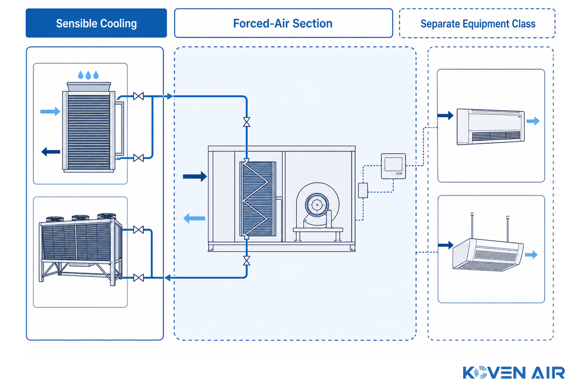
Dry cooling coils perform sensible cooling: they reduce air temperature without intentionally removing moisture. Wet cooling coils use condensation to remove latent heat. A dry cooler from outdoors dissipates heat to ambient air from a closed fluid loop. Yet all three can work in different circumstances, despite similar names.
The equipment class matters as much as the word “dry.” The AHRI applied-sector index lists active chilled beams under AHRI 1240/1241, while forced-circulation air-cooling and air-heating coils sit under AHRI 410. Room fan coils are also listed separately. That taxonomy is a useful first gate:
- Forced air moves through an AHU, MAU, or FFU section: this guide’s selection and evidence method is relevant.
- For systems that induce room air through chilled beams, follow the selected beam’s rating basis and its own condensation-control rules.
- A packaged room fan-coil unit uses a separate rating and service basis. Let’s check the rating, drain, filter, sound, and service requirements.
- This unit sits outdoors and rejects process-fluid heat. This means it’s a dry cooler and not the indoor DCC unit discussed here.
Cleanroom classification does not close this gate. ISO 14644-1:2015 classifies air cleanliness by airborne particle concentration. Its public scope does not rate coil capacity, confirm pressure drop, or certify noncondensing operation. Those outcomes still need equipment data and site acceptance evidence.
Equipment terms that should not be merged
| Equipment type found in a search or schedule | Usual duty | Boundary for this guide |
|---|---|---|
| Indoor heat exchanger or heat exchange coil | Transfers heat between forced air and a cooling medium, commonly chilled water or water and glycol | In scope when it is selected for sensible, noncondensing duty. |
| Outdoor fluid cooler or air coolers | Reject heat from a closed circuit and its cooled fluid to ambient air | Outside this guide; these dry coolers and condensers use a different selection basis. |
| Air-cooled condenser, air cooled condensers, or gas coolers | Reject heat from a refrigeration circuit | Outside this guide; a condenser is not the indoor chilled-water coil discussed here. |
| Cooling tower or evaporative condensers | Use evaporative cooling for heat rejection | Outside this guide and subject to different water, hygiene, and operating requirements. |
| Adiabatic or evaporative assist | Pre-cools entering ambient air for an outdoor heat-rejection device | Adiabatic cooling changes the outdoor equipment category; it is not proof of a dry indoor coil. |
| Air conditioning systems | May combine sensible and latent cooling for comfort or process temperature control | Only the indoor coil and its interfaces are in scope; the whole cooling system is not being rated here. |
This distinction is important for specifications of industrial cooling. The required heat transfer rate is defined by the sensible heat load, the air and fluid states, the flow rate, the temperature difference, the heat transfer area, and the heat transfer surface. For a cleanroom buyer, the hidden risk is an equipment-class mismatch because an official standard scope can be mistaken for a project acceptance claim. Koven Air treats the rating basis, application duty, and site proof as separate decisions. A term shared by several HVAC systems doesn’t make their rating methods interchangeable, and any energy efficiency comparison must use the same duty and system boundary.
2. Build a Dew-Point Guard-Band Worksheet around the coldest surface
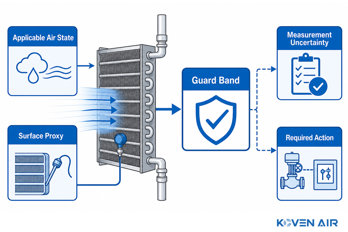
The governing relationship is simple: condensation can form when air contacts a surface below its dew point. NOAA illustrates this idea in its dew-point lesson. Applying that boundary to a coil is harder because neither room dew point nor chilled-water supply temperature necessarily describes the worst local condition.
Define the working margin for each operating case as:
Guard band = lowest supported active-surface temperature − applicable local air dew point
Having a positive calculated value is just the beginning. Now the project must determine how to build the surface proxy, how precise each sensor will be, how moisture will get in, and how to address transients. Use a supplier-validated calculation for the chosen geometry, flow, and load before treating chilled-water supply temperature as a stand-in for minimum surface temperature.
Dew-Point Guard-Band Worksheet
| Field | What to record | Why it changes the decision |
|---|---|---|
| Operating case | Design load, low load, startup, shutdown, door opening, humidity excursion, standby | The narrowest margin may occur outside peak sensible load. |
| Applicable air state | Dry-bulb, RH or humidity ratio, calculated dew point, location, timestamp | A room sensor can miss warmer or wetter air entering one coil section. |
| Surface proxy | Selected minimum surface temperature, measured tube/fin proxy, or documented model output | Fluid temperature alone is not proof of the coldest active surface. |
| Measurement uncertainty | Sensor accuracy, calculation method, calibration date, placement allowance | A small displayed margin may disappear inside combined uncertainty. |
| Latent-load owner | MAU, DOAS, desiccant unit, or other system; available capacity and failure mode | The dry coil cannot correct an entering-air moisture condition it was not selected to handle. |
| Required action | Normal modulation, high-dew-point alarm, valve limit, trip, recovery, operator response | A margin becomes useful only when it drives a defined response. |
There’s no universal safe margin for all coils, sensor networks and facilities. The allowance necessary should be derived from the uncertainty and consequence analysis for the project. Demonstrate this during the commissioning process. A narrow process tolerance, high-value production area, or slow humidity response may justify stronger sensing and a larger documented allowance than a stable comfort-cooling application.
Illustrative worksheet entry
The following entries illustrate the way that units and paired evidence are recorded. These are arithmetic examples, not Koven Air selection data or recommended acceptance values.
| Evidence type | Illustrative entry | Required project check |
|---|---|---|
| Entering air | 24.0 °C and 50% RH; calculated dew point 13.0 °C | Verify the formula, location, and coincident readings. |
| Leaving air | 17.0 °C; air temperature difference 7.0 °C | Compare with the selected duty and measured airflow. |
| Surface proxy | 16.5 °C; displayed guard band 3.5 °C | Confirm the proxy represents the coldest active surface. |
| Sensor capability | Temperature accuracy ±0.3 °C with 0.1 °C display resolution; RH accuracy ±2% | Include combined uncertainty in the project allowance. |
| Water temperatures | 16.0 °C supply and 18.0 °C return | Check the values at the coil, not only at the plant. |
| Water flow | 86 L/min | State the verified measurement method and valve position. |
| Air quantity | 5,000 m³/h at 1.6 m/s face velocity | Check distribution as well as the total. |
| Sensible duty | 12 kW | Reconcile air-side and water-side calculations. |
| Design pressure record | 80 Pa air-side and 15 kPa water-side | Compare each value with its separate available budget. |
| Trend evidence | 1 min samples across a 2 hour witnessed test | Retain time-aligned raw values and calculation outputs. |
| Low-load case | 2,500 m³/h, 45 L/min, and 6 kW | Verify control stability and the dew-point margin again. |
| Humidity excursion | 24.0 °C and 65% RH; calculated dew point about 17.0 °C | Use the project’s approved psychrometric calculation. |
| Protective response | Illustrative limit 18.0 °C with a 30 s response record | Substitute the project-approved limit and delay. |
| Recovery record | 15 min observation plus 2 hours stable operation | Substitute the approved recovery test duration. |
3. Apply the Three-Budget Coil Rule
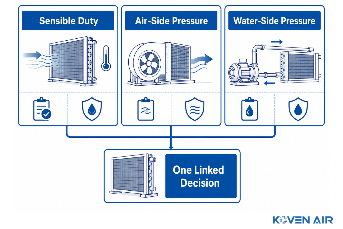
A coil that meets sensible duty but consumes too much fan or pump head isn’t a successful selection. It should be treated as one linked decision across three budgets, not three decisions checked late.
| Budget | Selection evidence | Common failure if ignored |
|---|---|---|
| Sensible duty | Entering/leaving air states, airflow, fluid temperatures and flow, load cases, stated rating method | Room temperature drifts or the valve stays saturated at high load. |
| Air-side pressure | Clean-coil drop at scheduled airflow, allowance for filters and other sections, available fan/FFU external static pressure | Actual airflow falls below the value used in the duty calculation. |
| Water-side pressure | Coil drop at scheduled flow and fluid, circuiting, valve authority, branch balance, available pump head | Design flow is not delivered or control becomes unstable at low load. |
Rows, fin geometry, face area, tube layout, and circuiting affect both heat transfer and pressure drop. There’s a limit to increasing capacity with surface area because pressure drop can rise with it. Koven Air’s public solution page has project-specific comparisons, so those values should remain project-specific. The correct answer for the actual state of air and fluids is a scheduled selection, not a copied row-count rule.
The air budget also covers the adjacent system. A named P.E. writing in HPAC Engineering shows how overlooked system pressure can impact air handling equipment. For an FFU return path, confirm that the selected coil, filters, grilles, casing, and duct path fit the same available static-pressure envelope.
A 2025 cleanroom study treats the chilled water and air systems as an integrated whole rather than as individual components. Since the specific savings are associated with the configurations and the climate of the study site, savings attributed to this study can’t be generalized to another plant. The transferable point is narrower: The main point here’s that part-load fan and pump behavior belongs in the coil decision.
Ask Koven Air to review a dry coil input schedule after all three budgets and the dew-point cases are defined.
4. Complete the coil input schedule before requesting a selection

A useful schedule lets another engineer reproduce the design case and identify what remains assumed. “Airflow, water temperature, and capacity” isn’t sufficient. For an industrial buyer preparing an RFQ, ambiguous units create a mismatch that can delay selection because the supplier can’t verify the same design case. Koven Air can then compare the schedule against the selected duty. Provide the units, for example, °C or °F for temperature, kW for duty, Pa for air pressure, kPa for water pressure, m³/h or L/s for airflow, and L/min or GPM for liquid flow, so a supplier need not guess the units.
Air and environment
- Airflow at each required operating case and the calculation basis.
- Entering dry bulb temperature plus RH, wet-bulb, humidity ratio, or dew point; state the location and coincidence assumptions.
- Required leaving dry-bulb and any allowable temperature variation.
- Velocity of face air and its degree of uniformity. State if the case or upstream section can cause a high-velocity zone or bypass.
- Altitude, cleanliness class context, particle-control constraints, and applicable corrosion or material conditions.
- Maximum clean coil air pressure drop and the total air path pressure budget.
Fluid and coil
- For each case, supply and return chilled water temperatures, required flow of chilled water, the fluid type and glycol, with a concentration of glycol if present. Avoid the undefined label “cooling water”.
- Maximum water-side pressure drop, available branch differential pressure, valve type, and intended valve authority.
- Available face dimensions, casing limits, connection hand, access space and the installation orientation.
- Tube, fin, casing, flange, and any condensate drain pan materials needed for the environment.
- Rows, fins, circuiting, fouling assumptions, and the rating or test basis proposed by the supplier.
Control and acceptance
- The latent-load owner and its design and off-design ability to hold the entering-air state.
- Dew-point and surface-temperature proxies, sensor locations, stated accuracy, alarms, trips, and reset logic for temperature and humidity control.
- Failure positions for valves and pumps, freeze protection where relevant, startup and shutdown interlocks, and recovery ownership.
- Test points witnessed, required instruments, specified intervals for trending, the acceptance period, and documents required at handover.
- Include occupied-zone comfort and acoustic criteria when coil selection may affect them.
AHRI 410 provides some restrictions such as frosting conditions, microchannel coils, bare-tube coils, and non-round-tube coils. Confirm applicability rather than writing “AHRI 410” into a schedule as a generic quality badge. A rating basis shouldn’t be considered the same as third-party certification, and neither should replace site acceptance.
5. Make the controls prove the dry operating envelope
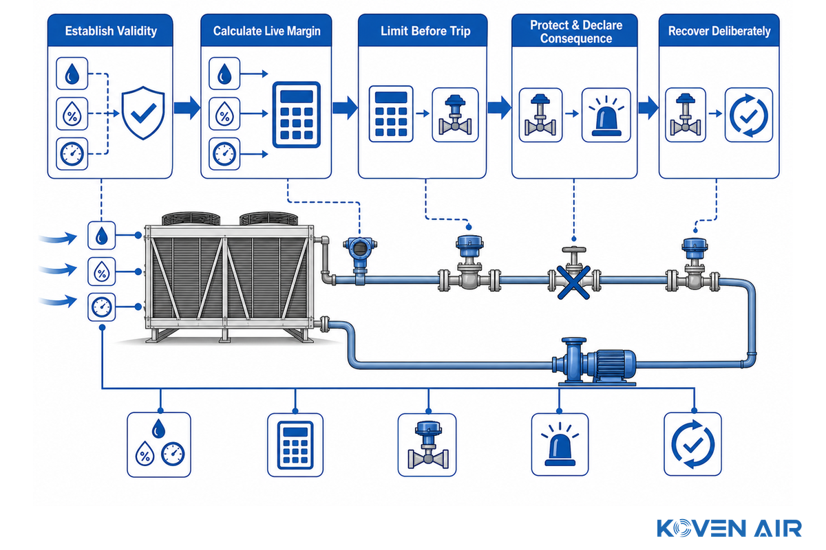
Using the completed input schedule, the control sequence should turn measured risk into a defined response. At least, trend the relevant entering-air condition and the temperatures of the fluid supply and return, valve command and position (if available), airflow or its accepted proxy, and the selected proxy for the surface temperature. Calculate dew point from calibrated temperature and humidity measurements, and record both the equation and sensor inputs.
- Establish Validity. Reject or alarm implausible sensor values before they enter the guard-band calculation.
- Calculate the live margin. Use the local air state and the supported surface proxy (not a convenient remote room value).
- Limit before trip. When margin narrows, apply the approved valve, water-temperature, or airflow constraint while watching room temperature.
- Protect and declare consequence. If the trip point is reached, protect the coil area and alarm the responsible operator. Closing a valve may prevent moisture damage, but it also removes sensible-cooling capacity.
- Recover deliberately. Define sensor-validity checks, minimum stable time, operator acknowledgement and process conditions, prior to resuming normal control.
The latent-load owner is part of this sequence. Outdoor-air drying, infiltration control, door management and internal moisture loads establish the entering-air dew point. If that system can’t hold its envelope, no local coil routine can create missing dehumidification capacity.
An ACHR News case study reports the use of an MAU coil in a special dry-cooler mode. It’s a different duty, but the lessons learned from developing the mode aren’t equally applicable to this case; only the commissioning measurement lesson transfers. Valve position, pump operation, balancing, mode changeover, and dew-point logic had to be measured together. Those settings wouldn’t apply to an indoor cleanroom DCC. A reviewed patent also describes a surface sensor tied to dew-point control, which shows an available architecture, but doesn’t define a required universal solution.
6. Commission with an evidence ladder
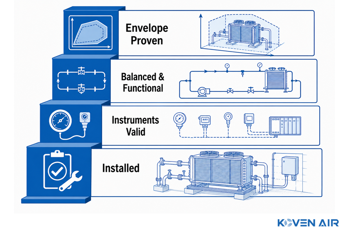
“The coil looked dry” is the bottom rung, not acceptance. Develop the record in four levels. For a cleanroom facility team, the risk is a passing visual check with no verified instrument baseline. Because NIST treats fault detectability as condition-dependent, the commissioning record must connect each measured state to an acceptance criterion rather than a guess.
| Level | Evidence | What it can prove |
|---|---|---|
| 1. Installed | Correct model/selection, orientation, connections, access, insulation, sensor locations, valve and flow direction | The physical installation matches the reviewed submittal. |
| 2. Instruments valid | Calibration records, point-to-point checks, dew-point calculation check, valve feedback, airflow and water-flow method | The later trend is based on credible signals. |
| 3. Balanced and functional | Measured airflow, fluid flow, both pressure drops, valve stroke, pump/valve interaction, alarm and interlock tests | The system can reach its scheduled operating points and protective states. |
| 4. Envelope proven | Time-aligned trends at design, low-load, startup, humidity-excursion, trip and recovery cases | The margin and room outcome hold through the agreed envelope. |
Record the as-left values and software/sequence revision used during the test. A passing result in one project can’t be presumed for another. Even on the same site, a subsequent change to a filter, airflow reset, replacement of a valve, repositioning of a sensor, or even the replacement of a dehumidifier, may affect part of the baseline.
When considering evidence related to a proposed cleanroom, separate thermal and particle evidence. The particle-classification record answers a different question from the coil’s psychrometric, hydraulic, and air-side acceptance record. Both may be required, but one can’t be used as a proxy for the other.
7. Troubleshoot and maintain from measured proof
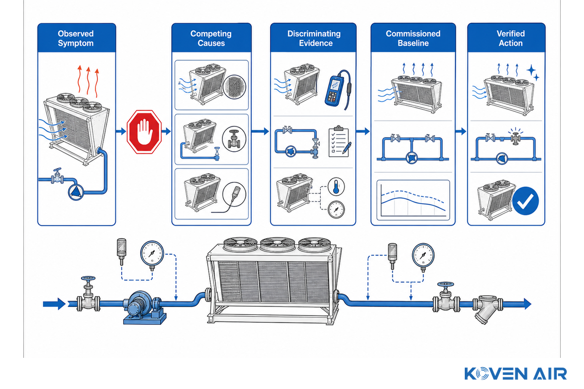
Once the commissioning baseline is set, a symptom is a signal to investigate, not a diagnosis. NIST’s work on AHU and cooling-coil fault detection looks at what faults can be detected and the circumstances leading to detection. It analyzes the role of selected variables, approximation error, fault size, and the external environment. Use the matrix below to test competing causes against the commissioned baseline, rather than identify one most likely cause.
Fault-to-Proof Matrix
| Observed symptom type | Competing causes | Discriminating evidence | Do not conclude yet |
|---|---|---|---|
| Leaving air too warm | Low airflow, low water flow, warm supply water, valve limit, load above schedule, fouling | Air and water flows, entering/leaving states, valve command/position, clean baseline | “Coil is undersized” |
| Room temperature drifts at low load | Valve rangeability, sensor bias, minimum flow, unstable pump differential pressure | Valve stroke trend, branch differential pressure, calibrated room/air sensors | “More rows are needed” |
| Guard band collapses | Humidity excursion, colder fluid, bad surface proxy, local bypass air, sensor drift | Time-aligned dew point, surface proxy, fluid temperatures, door/MAU status | “Water setpoint is safe” |
| Moisture appears at one edge | Air bypass, uneven circuiting, insulation gap, local infiltration, sensor placement | Surface-temperature traverse, smoke/air-path check, insulation inspection | “Whole coil is wet” |
| Air pressure drop rises | Fin loading, filter loading, wet surface, airflow measurement error, blocked path | Section-by-section differential pressure at matched airflow and condition | “Clean the coil immediately” |
| Water pressure drop changes | Flow change, valve position, branch balance, air lock, internal restriction, instrument error | Verified flow, differential pressure, valve/pump state, instrument zero check | “The coil is internally fouled” |
| Valve stays near 100% | High load, low flow, warm water, low airflow, control scaling, lost capacity | Full energy balance and actuator feedback at the same timestamp | “Valve is too small” |
| Frequent condensation trips | Real moisture events, narrow set margin, noisy sensors, poor placement, unstable control | Raw sensor trend, calibration, event sequence, independent spot measurement | “Disable the alarm” |
| Fan or pump energy rises | Pressure reset, filter/coil loading, flow imbalance, changed setpoints, control hunting | Matched-load trend of flow, pressure, speed, valve position, and thermal duty | “The coil alone caused it” |
Matrix Limitations: This matrix directs a cause-and-effect investigation. Matrix limitation: It doesn’t supply diagnostic values. Define diagnostic values from the commissioned clean baseline, the capability of the sensor, the manufacturer’s limit, and the facility’s consequence analysis.
Trend-to-Trigger Maintenance Ledger
Do not replace scheduled inspections with dashboards. The public preview of ANSI/ASHRAE/ACCA Standard 180-2018 keeps baseline task frequencies, then uses condition indicators, trended objectives, documented unacceptable conditions, and review of repeated results to adjust the maintenance plan. The same is true for the DOE guidance describing BAS trend data as a stronger basis for baselining and measurement and verification.
| Baseline item | Trend or inspection signal | Triggered action | Owner and closeout |
|---|---|---|---|
| Matched-airflow coil pressure drop | Persistent deviation from the clean, dry baseline | Verify airflow and wetness, inspect face/bypass, then decide whether cleaning is justified | Facility technician; record before/after values |
| Matched-flow water pressure drop | Persistent change beyond instrument repeatability | Check instrument zero, valve, balance and air before internal inspection | Hydronic lead; update branch record |
| Guard-band distribution | More time near the project alarm band | Audit latent-load owner, sensors, water reset and local surface proxy | Controls engineer; retain event timeline |
| Valve position versus duty | More valve command for the same verified load | Check flows, heat-transfer states and actuator feedback | Controls plus mechanical team; close with a matched-case retest |
Poor results from two inspections may allow a review toward more frequent task intervals. Two inspections showing acceptable results may allow a review of whether task frequency should change. Neither of these results mandates any change. Document the review, follow manufacturer instructions, and keep the minimum requirements that apply to the equipment and facility.
8. Know when a dry coil is the wrong fit
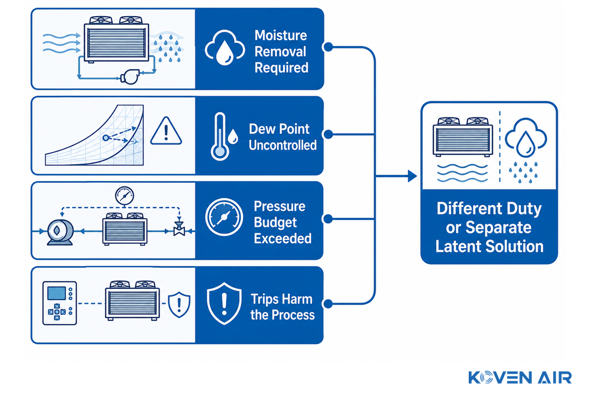
Add a different duty or a separate latent solution when any of the following conditions is true. When outdoor-air treatment owns that latent duty, review how a make-up air unit can condition and dehumidify the entering air.
- The coil is expected to remove moisture intentionally.
- The entering air dew point can’t be contained within a specified range.
- The selected surface is below the margin required to satisfy the sensible capacity.
- The selected coil’s pressure can’t be supported by the fan or pump.
- Frequent changes in humidity can cause protective trips that leave unacceptable process-temperature outcomes.
- First identify the equipment class—chilled beam, room fan coil, refrigerant coil or outdoor dry cooler—because each follows a different rating and service framework.
A drain pan can only limit damage that happens in an off-design event. It can’t change an uncontrolled condensing service into a specified dry coil service. Setting the temperature of the chilled water high won’t make up for an underspecified latent load system. For a cleanroom buyer, the hidden risk is a duty mismatch because a protective trip can leave the process without its required sensible capacity. Koven Air should receive the rejected operating case as part of the RFQ, not just the preferred case. You must describe the moisture duty properly before selecting the scope of the equipment. GMP projects with sanitary-construction and traceability requirements can continue to Koven Air’s pharmaceutical dry cooling coil page.
9. Turn this guide into a supplier brief
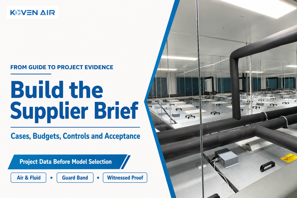
After rejecting the wrong equipment duty, the fastest useful supplier conversation starts with the completed input schedule, not a model request. Include the air and fluid cases, three pressure/duty budgets, the proposed guard-band method, control points, and the witnessed acceptance plan. Because the RFQ now states each risk, assumption, and acceptance test, Koven Air can identify a mismatch before a quotation is prepared. Request that the supplier provide the exact rating basis, selection output, geometry and materials, circuiting, pressure drops, connection drawing, and exceptions list.
The current product line and project-specific selection of Koven Air’s dry cooling coil solution page can be used for current product-line information and project-specific selection, not to construct this guide’s engineering evidence. Use this guide to prepare the engineering evidence; use the solution page when the project is ready for a selection. The info relating to Koven Air and the manufacture of the products can be found on the About Koven Air page.
To commence the review process, open the project contact form and submit the coil schedule.
Frequently asked questions
What temperature should chilled water be for a dry cooling coil?
There’s no universal supply temperature. Choose water temperatures from the coil geometry, flow, airflow, sensible duty, local entering-air dew point, surface-temperature model, sensor uncertainty, and all operating cases. The acceptance question is whether the coldest supported surface maintains the project guard band, not whether the water matches a common rule of thumb.
Can a dry cooling coil still produce condensation?
Yes, during off-design conditions or a fault. A humidity excursion, colder-than-expected fluid, uneven surface temperature, air bypass, damaged insulation, sensor error, or control failure can erase the margin. That’s why the sequence needs alarms and a defined protective response, and why commissioning must test more than one mild, steady condition.
Is a dry cooling coil the same as a dry cooler?
No. An indoor dry cooling coil cools forced air with chilled water, while an outdoor dry cooler rejects loop heat to ambient air. They belong to different AHRI equipment categories and use different rating bases, operating boundaries, and service requirements.
Does ISO 14644 prove that a dry coil is suitable for a cleanroom?
No. ISO 14644-1 classifies airborne particle concentration; it does not rate a coil or certify a noncondensing operating envelope. A project still needs a supported thermal selection, material and cleanliness requirements, air and water pressure budgets, a dew-point control method, and commissioning evidence. The cleanroom record should classify airborne particles separately from the coil acceptance results while identifying the system interfaces. It should, however, present the guard band results for the coil acceptance along with the other results.
How often should a dry cooling coil be cleaned?
Base the cleaning interval on manufacturer instructions, facility rules, surface inspection, matched-airflow pressure drop, and capacity evidence. Compare each reading with the commissioned baseline, investigate persistent changes before cleaning, and revise task frequency only from documented condition history over time.
References
References & Sources: These public sources define the rating, equipment-category, dew-point, fault-detection, and maintenance boundaries used in this guide.
- AHRI 410: public scope and exclusions
- AHRI applied-industry equipment categories
- ISO 14644-1:2015 public scope
- NOAA JetStream: dew point and condensation lesson
- ANSI/ASHRAE/ACCA Standard 180-2018 public preview
- U.S. DOE: EMIS capabilities, baselining, and fault detection
- NIST: detecting faults in building air-handling units
- LBNL: HVAC maintenance faults and performance degradation
- Energy: coordinated chilled-water and supply-air distribution in cleanrooms
- ACHR News: MAU cooling-coil retro-commissioning case
- HPAC Engineering: system pressure versus air-handler specifications
Factory Selection Support
Turn this guide into a usable HVAC RFQ package.
Share design conditions, airflow, temperature, humidity, process load, room use, and scope boundary. Koven Air can recommend a practical equipment route before quotation.
7equipment families
ISO / GMPcleanroom review
RFQscope comparison
What to prepare before quote
- Use settingCommercial building, cleanroom, hospital, data center, process area, or retrofit.
- Operating conditionsAirflow, load, temperature, humidity, static pressure, and duty hours.
- ConstraintsFootprint, access, hygiene class, material, controls, documentation, and delivery boundary.
Final equipment selection depends on local codes, project drawings, and confirmed site conditions.

![Horizontal Fan Coil Unit Project Guide [Step-by-Step]](https://kovenair.com/wp-content/uploads/2026/09/horizontal-fan-coil-unit-guide-featured-1-768x512.png)
![Vertical Fan Coil Unit: Design & Maintenance [Guide]](https://kovenair.com/wp-content/uploads/2026/09/vertical-fan-coil-unit-guide-featured-1-768x512.png)



![Commercial Rooftop Unit Guide: Types, Sizing & Costs [2026]](https://kovenair.com/wp-content/uploads/2026/07/commercial-rooftop-unit-guide-featured-2-150x150.png)