
Get in Touch with Koven Air Company

ISO Certification
Hydronic Fan Coil Unit
Hydronic Fan Coil Units, 2-Pipe & 4-Pipe Systems
Koven Air hydronic fan coil units are made for hydronic heating and cooling applications where the chiller plant does the work, not the refrigerant line: wall mount, concealed ceiling mount, ducted, and cassette styles, wired for 2-pipe or 4-pipe systems, with a control valve engineering standard for every unit that most fan coil suppliers won’t share.
- 2 & 4-Pipe: System configurations
- 2-Way / 3-Way / PICV: Control valve options
- 4: Mounting types: wall, ceiling-concealed, ducted, cassette

AHRI 440/441
Rating framework referenced
30.2%
System energy cut, 1,280-unit retrofit
3.3 yr
Static payback, same retrofit
Why Chilled-Water Fan Coils Underperform, And How Hydronic FCU Design Fixes It
A hydronic fan coil unit circulates room air over a hot or chilled water bearing coil connected to a central boiler, chiller, or air-to-water heat pump – no refrigerant line or compressor on the unit, and the central plant heats or cools every zone on the loop – often the same loop that supplies radiant floor heat or domestic hot water. Most of the underperformance service calls we get on hvac systems like this have nothing to do with the coil or the fan; they come down to what controls the water circulating through that coil.
You’ll frequently see two symptoms on chilled water fan coil systems: the temperature split between the supply and the return will be 1-2°C where 5°C was specified, and zones on the same loop will land anywhere between 22°C and 26°C depending on which one happens to be drawing water at that particular moment. One field report that was part of the review we conducted on this project summarized it this way: “a 3°C temp split, water quality problems, and air pulled into the loop via a return bleeder… the textbook result of an undersized static balance and no upstream strainer, not a faulty coil.” This particular phenomenon is so well-known in peer-reviewed literature that a 2024 systematic review actually reviewed and categorized solutions for what’s called low delta-T syndrome.[1] And the underlying reason for low delta-T is always the same: a control valve that has been selected by the pipe diameter, rather than by Kv, that’s operating at an authority too low to regulate the system as pressure drops – the same valve authority concept documented in the ASHRAE Systems and Equipment Handbook that we walk through in Section 4.
Our hydronic fan coil units were designed to fix this root cause, rather than work around it. For every configuration we sell, the unit will have a control valve authority calculation, not just a pipe size, and for any 4-pipe application, we’ll supply separate hot-water and chilled-water coils, so that heating and cooling zones on the same floor won’t compete with each other. It’s a dull fix, but it’s the fix that will restore the 1-2°C temp split to the 5°C stability that we see in the 1,280 unit retrofit documented below.
Scope Note, What a Fan Coil Unit Does, and Does Not, Do
Hydronic FCUs recirculate and condition the air that’s already in a room — they don’t introduce outdoor air. Ventilation and IAQ requirements for commercial buildings are handled separately, most commonly under ASHRAE Standard 62.1. On a project where code-required outdoor air isn’t being addressed by another system, we partner our fan coil units with a dedicated outdoor air system (DOAS) rather than asking the FCU to do a job it was never built for, and leave that side of the design to our DOAS rooftop unit line.
This air-side vs. outdoor-air-ventilation distinction is also the source of many preventable comfort complaints – a fan coil that’s “not cooling enough” is most often a ventilation load problem being attributed to the wrong piece of equipment. The trade-offs that truly make a fan coil project a success, by contrast to a spec sheet that stops at coil rows and CFM, involve pipe topology, valve authority, and standards-based rating – which is why this page is organized the way it is, with pipe topology up top and product catalog down bottom.
Koven Hydronic Fan Coil Unit Lineup, Models & Configurations
We manufacture hydronic fan coil units in four mounting families: a horizontal fan coil unit line, comprising ceiling-concealed and ducted units, and a vertical, floor-standing line, with wall-mounted and cassette options. Available in both 2-pipe and 4-pipe layouts, our units are a water-source terminal, rather than an air-source, compressor-driven appliance. Therefore, each model listed below connects directly to your chiller, boiler, or air-to-water heat pump loop instead of generating its own refrigeration. Every fan coil unit, regardless of family, ships with the valve-authority and ESP calculation that we explain above; there’s no “lite” model without it. This is also the reason why affordable hydronic fan coil units can sometimes be challenging to find in a catalog reseller; the calculation take time to do correctly, and skimping on it’s how a unit ends up cheap. A wall mounted hydronic fan coil unit and a ceiling mounted hydronic fan coil unit cover the two most common retrofit scenarios we see for hotels and offices, while commercial fan coil units for larger open-plan floors and residential hydronic fan coil units for individual suites share the same underlying valve-authority and ESP engineering described above.
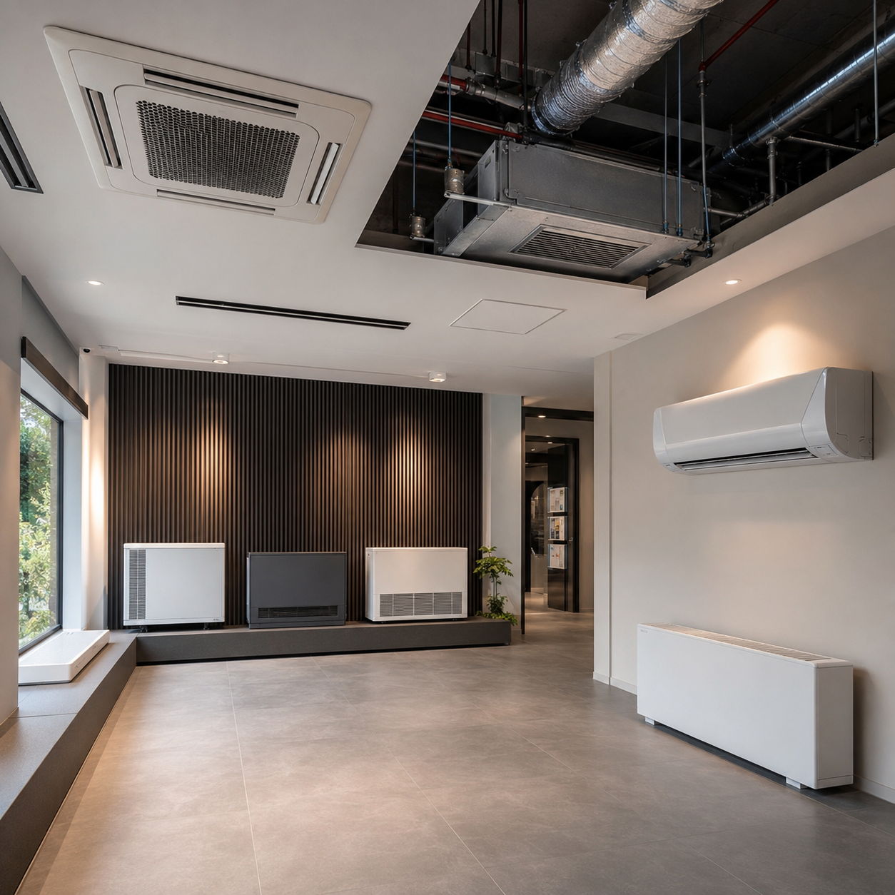
| Mounting Type | Typical Install Location | 2-Pipe Available | 4-Pipe Available | Best Fit |
|---|---|---|---|---|
| Wall-mounted | Exposed on exterior/interior wall | Yes | Yes | Hotel rooms, apartments, retrofit with no ceiling access |
| Concealed fan coil unit (ceiling) | Above drop ceiling, short duct runs | Yes | Yes | Offices, hospitality corridors, commercial floors — our highest-volume configuration |
| Ducted fan coil unit (uncased) | Ceiling void, longer duct runs | Yes | Yes | Multi-room zoning off a single unit |
| Cassette, ceiling mounted (4-way) | Flush ceiling mount, open-plan | Yes | Yes | Open-plan offices, retail floors, lobbies |
Size isn’t picked from the fixed product-tier in our catalog, but rather engineered from the actual load of your space – this pre-sales step that’s also called out in our guide to procuring is why we can’t show a generic table of CFM/tonnage here, as an application sized to an office hallway differs dramatically from one for a large, open trading floor, though the same families can sometimes mount to the same ductwork. We’re consistent on two sizing variables across the entire fan coil product line regardless of building scale, though: sound levels are always maintained within industry standards for occupied spaces, as defined by AHRI’s applied-fan-coil sound rating methodology, and the unit’s ESP is specified based on the specific ductwork system it’s feeding rather than a generic value that assumes a direct, unobstructed connection. Even open-plan spaces that use ceiling-mounted units receive the same precise, load-based sizing as our smallest wall-mounted models – there’s no “commercial applications” grade of unit that skips this process.
Buyer Note
Sizing is unique for every application, so the quickest way to get an accurate dimensional spec sheet for a fan coil product is through a brief conversation — we’ll just need the room-by-room load or square footage, the desired distribution (2-pipe or 4-pipe), preference for ceiling mount or other (or even no ceiling space to use), and your required control input (thermostat or BMS-controlled). We then use this data to provide a preliminary model suggestion and drawings package during pre-sales-request a quote to initiate that discussion.
While any ductless, non-ducted terminal, such as a baseboard radiator in an individual room, will offer limited control for each space it serves, our fan coil product can deliver independent room-level control across multiple zone floors with a single water loop feeding dozens of heads, even in the largest spaces. We also provide the hydronic fan coil units as an intermediate solution for room-and-zone level installations below the scale of a whole-building-ducted system where you don’t need the complexity of a single building hydronic air handler.
An improperly applied mounting type for the application is an expensive mistake to catch late in construction, such as specifying a ceiling-concealed unit for a hotel hallway where no ceiling cavity is available. This could require expensive, time-consuming rework on a project where much of the framing is already complete; our pre-sales process includes a review to ensure that mounting type and application are appropriately paired. Koven Air’s fan coil units are manufactured and individually tested at our 20,000 m² facility prior to shipment, meeting both the same sound and ESP parameters cited above, eliminating surprises upon delivery. Koven Air is engineered to run that same valve-authority and ESP sizing routine on every unit we export to 35 countries, not only the models a distributor chooses to stock. The reason low-cost catalog listings skip it isn’t laziness – unlike a spec sheet that shows a mounting photo and a tonnage number, the real risk sits in whichever line item got cut to hit a lower quote, and the mistake rarely shows up before the first cooling season.
4-Pipe vs 2-Pipe Fan Coil Systems, Simultaneous Heating & Cooling
This initial decision influences many downstream choices, especially which of the two valve configurations outlined in the following section would be appropriate. Whether using a shared coil heat exchanger or separate chilled water cooling coils and heating coils, each fan coil is designed for optimal thermal performance.
| Factor | 2-Pipe System | 4-Pipe System |
|---|---|---|
| Coils per unit | 1 shared coil | 2 dedicated coils (hot + chilled) |
| Simultaneous heat/cool by zone | No — whole loop switches season by season | Yes — every unit chooses independently |
| Piping runs to each unit | 2 (supply + return) | 4 (hot supply/return + chilled supply/return) |
| Typical use case | Single-season-dominant buildings, tighter first cost | Hotels, mixed-use, hospitals — sun-exposed and shaded zones with different loads on the same day |
| Installed cost vs 2-pipe | Baseline | Higher (extra coil + 2 more pipe runs per unit) |
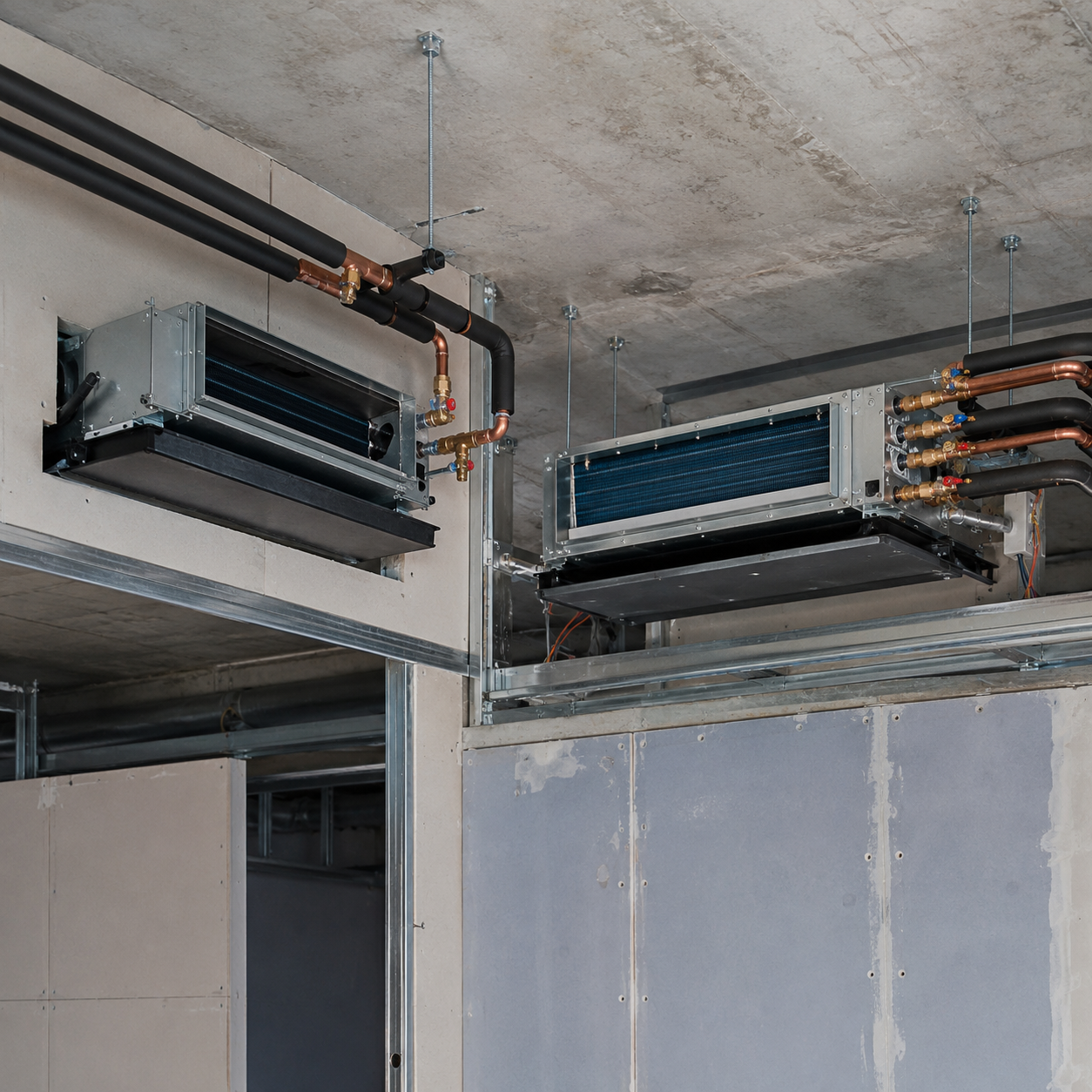
Engineers don’t actually argue over the number of pipes – the real trade-off is what happens to the coil once you’ve selected the system. A higher supply/return delta-T means less flow, and therefore smaller pipe, to meet a given load – that’s precisely the idea behind fixed-delta-T control we see in the results. But delta-T can’t be forced arbitrarily high – you need a deeper coil with more fin rows to accomplish a large delta-T, and deeper coils have higher air-side pressure drop and coil faces that can be difficult to clean.[2] Koven Air specifically designs to the coil-depth trade-off, using identical, factory-verified, fin-and-tube tooling across the 2-pipe and 4-pipe family, as opposed to using the deepest possible coil to fill the cabinet. Koven Air is engineered to hold that same tooling standard across every unit we ship to 35 countries, not just a premium SKU – unlike catalog resellers that swap in a deeper stock coil and call it a 4-pipe upgrade, the trade-off is disclosed on the spec sheet instead of surfacing as a field risk after commissioning. AHRI Standard 440/441 performance-rating testing applies the same way to both the 2-pipe and 4-pipe configuration of a given coil family, so published ratings stay comparable across the choice covered in this section.
4-pipe distribution earns back its added cost fastest when cooling and heating loads coexist during the same hour – a south-facing meeting room, coupled with a north-facing office down the hall; a hotel corridor requiring morning temperature moderation, while rooms are cycling between cooling and heating by occupants. This disparity is often left unresolved on 2-pipe systems, or addressed via an electrical supplemental heat – on a 4-pipe system, this condition is managed simply by the design of the circuit, regardless of the hour of the day or the part-load condition within the building. A 4-pipe fan coil layout only delivers on that promise if the plant behind it can actually produce separate hot and chilled water streams simultaneously – see our 4-pipe heat pump chiller vs. standard chiller-and-boiler comparison for how that source-side choice affects a 4-pipe fan coil project.
2-Way vs 3-Way vs PICV Control Valve, Which Fits Your Hydronic FCU Project?
Valve Authority Compliance Grid – the fan coil valve calculation most providers neglect, and the one that decides whether guest comfort issues ever go away.
Valve authority is the ratio of the control valve’s pressure drop to the total pressure drop across the circuit it controls: N = ΔP(valve) ÷ [ΔP(valve) + ΔP(circuit)]. Authority isn’t some abstract number; it’s the measure of whether a valve modulates smoothly, or acts like a simple on-off switch irrespective of its command. Common engineering guidelines, including the ASHRAE Systems and Equipment Handbook chapter on hydronic system control, identify three levels of authority: Below approx 0.25-0.3 the control is unstable; the range 0.3-0.5 provides fair-to-good control; and values above 0.5 ensure excellent, close to linear control (exact limits can vary but direction remains consistent)[3]. In reality, most control valves are installed undersized from an authority standpoint, not undersized relative to their pipe sizes (as in pipe sizing, which can be far worse), but to achieve adequate flow on the circuit, which results in a well below 0.25 authority before the valve is even placed into service. In fact, the cheapest valve bid on a project can carry the greatest hidden cost: if the authority calculation is performed incorrectly, it can result in an expensive re-commissioning trip and balancing session before the first cooling season is over-an issue we’ve observed many times.
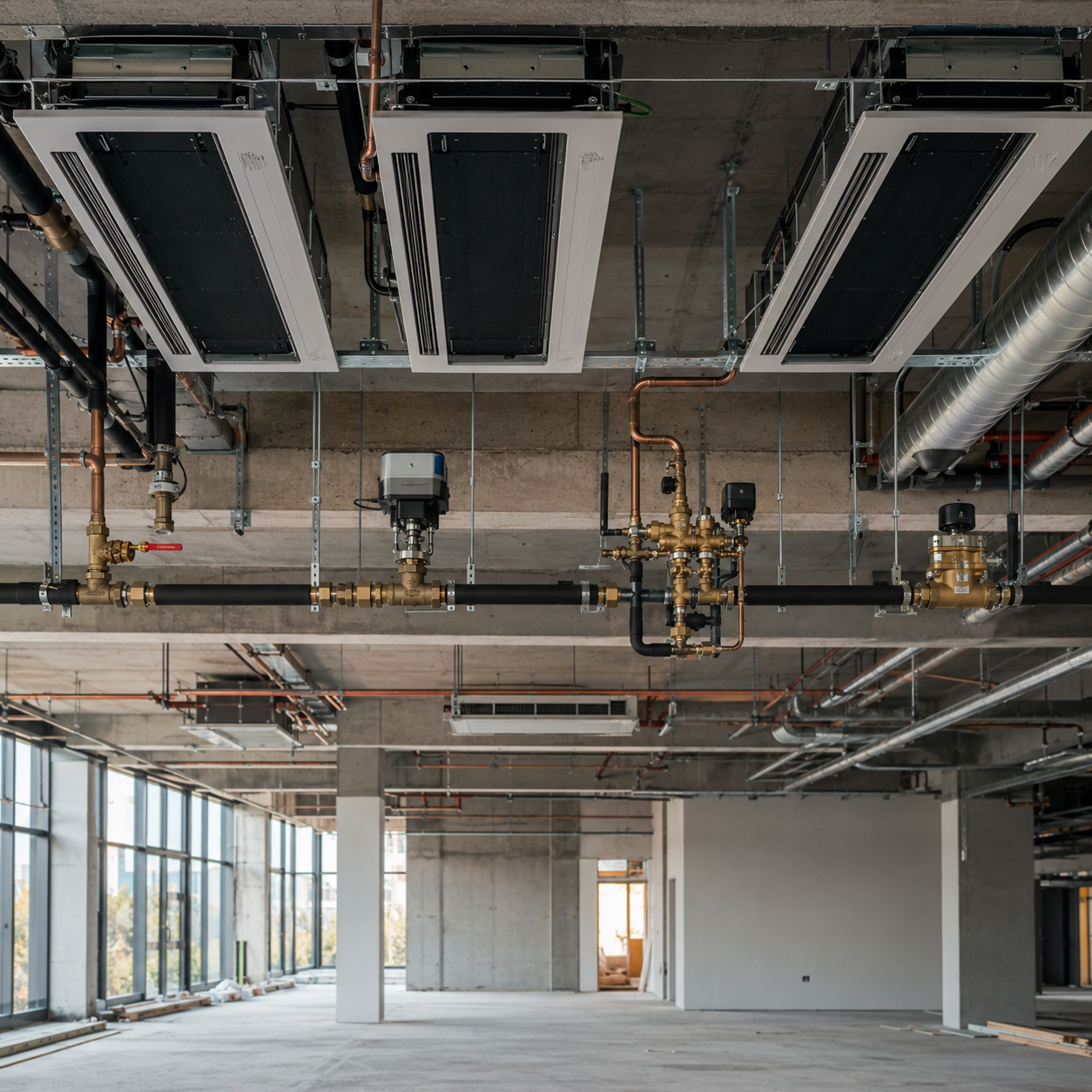
| Valve Type | Flow Behavior | Authority Sensitivity | Hydraulic Balancing | Best Fit |
|---|---|---|---|---|
| 2-way on/off | Variable flow, full open/closed only | Low sensitivity (binary) | Needs separate balancing valve | Residential, standard offices — economical with a VFD pump |
| 2-way modulating | Variable flow, continuous 0-10V/4-20mA | Degrades sharply below 0.25 authority | Needs separate balancing valve | High-end offices, hotel rooms needing tight temperature control |
| 3-way (diverting) | Constant flow — excess water bypasses the coil | Insensitive to authority by design | Built-in branch constant-flow | Older constant-flow retrofits; pump runs full speed always |
| PICV | Variable flow, pressure-independent | Innate authority of 1.0 — insensitive to upstream pressure swings | Built-in dynamic balance, no separate balancing valve | High-rise, hotels, large public buildings — current mainstream for variable-flow systems |
PICV performance is a loop-level outcome, not a standalone valve trick – your savings will depend on the scope of the hydraulic loop, and the pump control strategy it’s matched to – as a 2023 peer-reviewed evaluation makes clear when it compares PICV installations at the system level rather than the single-coil level. [4] Appropriate valve authority is also the direct fix for uneven comfort across zones – the “one room runs cold, its neighbor runs hot off the same loop” complaint from Section 1. Paired correctly with a VFD pump, the mechanism is straightforward: as zone loads drop, the valves close down, loop differential pressure rises, and the VFD slows the pump in response, cutting pump energy sharply. None of this happens on a 3-way constant-flow system, where the pump runs flat out regardless of load.
20-50%
Energy savings range reported in valve-manufacturer technical literature for PICV retrofits over conventional 2-way/3-way control, with payback typically under 3 years
Source: Danfoss PICV technical documentation[5] — vendor-published figures, cited as directional industry context rather than a guaranteed or Koven-specific result; actual savings depend on system-specific conditions. Our own measured retrofit result (below) falls inside this reported range.
“The valve calculation is the one step buyers skip because it doesn’t show up on a spec sheet the way tonnage or CFM does. We run valve authority for every 2-way modulating and PICV order before it ships, it’s a five-minute calculation that prevents a six-month comfort complaint.”
Two common installation errors account for most of the valve-related callbacks we see: mounting the actuator “upside-down” so that water runs down the stem, which will destroy the actuator over time; or failing to install the upstream Y-strainer so that the valve plug jams on the very first startup flush when the amount of sediment is the greatest. Both issues are detailed in our installation guides, and both will never appear on a valve datasheet.
With the right valve type selected, a couple of connection-level details will put it over the top: ensure both pipe runs on either side of the valve are insulated to prevent water from dripping outside of the drain pan; select valve and seal material compatible with your water quality to ensure long-term service life without corrosion; and be certain the actuator voltage and control signal match your BMS or thermostat before shipping – not after. These aren’t sexy items, and are none-the-less the difference between a system that will continue to rebalance itself as building loads change and one that requires a service call every cooling season.
Real-World Results, 1,280-Unit Retrofit Cuts System Energy 30.2%
High-Flow-Low-Delta-T Diagnostic
How we identified and fixed the exact syndrome described above in Section 1, at building scale.
A 68,000 m² mixed-use tower (finance office floors, hotel, retail podium; 38 levels above and 4 below grade) recently completed a central-AC retrofit over March-June 2024 on its 12-year-old, 1,280-unit conventional fixed-frequency fan coil units plant. The problem prior to the retrofit was a classic low-delta-T symptom and it was a cost too great to tolerate: a constant 7°C chilled-water supply set point, irrespective of the actual load; a 1-2°C split between the supply and return rather than the expected 5°C; severe hydraulic imbalance, causing some zones to operate at below 22°C while others idled above 26°C; and a 12% tenant-satisfaction issue the owner could no longer ignore. The cost in pump energy alone accounted for 32% of the system’s energy consumption – the price of pushing excess water across a delta-T too narrow to be effective.
Three separate changes made up the fix: a reset of variable supply-temperature strategy to ambient conditions (7°C above 32°C ambient; increasing to 9°C in the 26-32°C range; falling to 11°C below 26°C; maxing out to 10-11°C in the shoulder seasons when chiller COP exceeded 5.2); a retrofitted fixed-delta-T terminal control on all 1,280 units; the KA19 smart controller which was added by Koven Air held a 5°C setpoint and controlled both valve position and fan speed automatically to meet that target; and an upgrade on the pump-side from three constant-speed chilled water pumps to variable frequency drives operating on a joint differential-pressure-plus-delta-T control logic. Because the retrofit involved reusing the fan coil body and just upgrading the motor and adding the KA19, it was 60% cheaper than full replacement and the use of a wireless commissioning sequence sliced about 70% off construction time compared to an equivalent rewired retrofit; the building never emptied. Chiller COP and system energy in the before/after figures below are tracked the same way a commercial building’s HVAC energy performance is defined under ASHRAE Standard 90.1, so the reported savings are directly comparable to code-driven efficiency targets, not a proprietary metric.
The worst loop end – the zone farthest from the pump, the one that always runs short first when a system is hydraulically out of balance – held to 24±1°C after the retrofit. That number matters more than the headline energy figure to a facility manager: it’s the proof that fixing valve authority and delta-T control, not just adding controls for their own sake, is what actually ends the “some rooms too hot, some too cold” complaint pattern described in Section 1. Unlike a controls-only retrofit that leaves the underlying hydraulics untouched, the standard fix here combined supply-temperature reset, terminal delta-T control, and pump VFDs – whereas a single-lever fix (say, controllers alone) would have left the flow-versus-load mismatch, and the pump energy waste it causes, in place.
| Metric | Before | After | Change |
|---|---|---|---|
| Indoor temperature swing | ±2.5°C | ±0.8°C | 68% tighter |
| Tenant complaint rate | 12% | 0.9% | -92.5% |
| Chilled-water supply/return ΔT | 1-2°C | ~5°C stable | Flow reduced 40% |
| Chilled-water flow rate | 850 m³/h | 510 m³/h | -40% |
| Pump energy | 520,000 kWh/yr | 286,000 kWh/yr | -45% |
| Chiller average COP | 3.5 | 4.6 | +31.4% |
| Total AC system energy | 3,800,000 kWh/yr | 2,652,000 kWh/yr | -30.2% |
Source: Koven Air project retrofit data, March-June 2024
3.3 yr
Static payback on ~RMB 3,000,000 total investment, at ~RMB 918,000/year in measured electricity savings
Koven Air project data — the same retrofit summarized above
Ratings, Standards & Manufacturing Quality
The rating standard fan coil buyers in the US should be checking any published data against is AHRI Standard 440 (I-P) / 441 (SI) – Performance Rating of Fan Coil Units, defining definitions, test methods, rating requirements, the published-ratings format and conditions of conformance to nameplate data that participating manufacturers are required to meet. [6] The most common energy standard in use for commercial projects in the US, ASHRAE 90.1, directly references AHRI 440 as the pathway to compliance with hydronic fan-coil-unit ratings. [7] A 2025 peer-reviewed field analysis of real installed fan coil units is worth mentioning here, because it quantifies why this requirement matters: it found a real, non-trivial discrepancy between advertised and as-built airflow, consistently smaller on certified equipment than on non-certified equipment. [8]
We perform testing according to these same rating principles in our in-house laboratory as part of the 24 hour aging and factory inspection outlined below. We don’t display a certification badge on this page, except when it’s backed up by a verified, current entry on the official listing. For current certification details for project submittals, please request current documentation from your Koven Air representative.
20,000 m²
Factory floor area
18 Processes
Standardized production line
36 Inspections
Per-unit factory quality checks
24-Hour
Aging test before shipment
In-House Lab
Chiller & heat-pump testing facility
Hydronic Fan Coil Unit Engineering & Diagnostic Tools
01
Valve Authority Calculator
Enter the control valve’s pressure drop and the rest-of-circuit pressure drop (coil + piping + fittings) to see the resulting valve authority, its control-quality tier, and which valve type fits that result — using the same authority formula and three-tier scale referenced above.
Access Calculator02
PICV Retrofit ROI Estimator
Estimate annual savings and payback for a PICV control-valve retrofit, using the 20-50% energy-savings range reported in valve-manufacturer technical literature (cited above) as the savings assumption. Enter your own numbers — outputs are directional estimates, not a guaranteed result.
Calculate ROI03
Low-Delta-T Diagnostic Quiz
Tap each symptom that matches your chilled-water fan coil system. This checklist mirrors the classic Low-Delta-T Syndrome contributors described above — it’s a self-diagnosis starting point, not a substitute for a full valve-authority calculation.
Start Diagnosis04
2-Pipe vs 4-Pipe Decision Guide
Answer three questions about your building to get a directional recommendation, based on the comparison logic covered above. This is a starting point for the conversation, not a substitute for a load-based sizing review.
Open GuideHydronic Fan Coil Unit FAQ
00
/ 09
A hydronic fan coil unit is an individual hvac unit in each room or space that warms or cools by pulling air through its filter and over a coil supplied with hot or chilled water from a central system like a boiler, chiller, or air-to-water heat pump – unlike a DX (refrigerant-based) fan coil, no refrigerant lines connect to the unit. When heating only, the equipment can be referred to as a hot water fan coil.
A 2-pipe system has only one supply and return line for the entire system, so hot or chilled water is supplied exclusively, switching from heating to cooling seasonally. A 4-pipe system runs separate hot and chilled water coils and piping to each terminal unit, enabling a space to heat and cool independently of other rooms or the season, though it does cost more due to the additional piping and coils.
It depends on the configuration, but many hydronic fan coil units don’t require ductwork. Wall and ceiling cassette units work within individual rooms. Ceiling-concealed or floor-standing units may have a few feet of duct run, connecting one or a few adjacent rooms.
Fan coil units are discrete terminal devices, usually in a room or zone, which condition the air already present in that space. An air handling unit (AHU) is a central system, often used to condition an entire floor or building through ductwork and provide outdoor air ventilation and filtration.
Yes. On a 2-pipe system the same coil carries either hot or chilled water on a seasonal basis. On a 4-pipe system a dedicated hot coil and chilled coil let a single unit heat or cool as needed, regardless of the season and regardless of what its neighboring zones are doing.
Yes, when operating in cooling mode. Warm air from the room passing across the chilled-water coil will cool below its dew point, causing condensate to form on the coil surface and drain through the unit’s drain pan and line – just like a refrigerant cooling system does to dehumidify.
The most-cited shortcomings – high maintenance requirements, noise levels, and reduced air distribution range compared to a full AHU – both derive from two things: having the coil, drain pan, and filter located within the space instead of in a mechanical room; and relying on a central plant that feeds the fan coil instead of having its own independent fresh air ventilation (like when it’s paired with a DOAS or AHU). Neither one is a reason to abandon fan coils – both are reasons to consider access and ventilation from the outset.
This is the “low-delta-T” (“high-flow-low-delta-T”) issue described in Section 1 – it almost always results from a control valve that doesn’t have enough authority (usually sized for pipe diameter rather than by Kv calculation), a 3-way bypass on a variable flow system, or a lack of a static or dynamic balancing valve. Fixing valve authority, usually with a pressure-independent control valve where appropriate, will solve this problem.
Fan coil unit price varies widely depending on mounting style, coil arrangement (2-pipe vs. 4-pipe), control valve selection, and the scale of the project, so a single number is misleading – see the Procurement Guide above for details, and request a project-specific quote for a real number.


![Commercial Rooftop Unit Guide: Types, Sizing & Costs [2026]](https://kovenair.com/wp-content/uploads/2026/07/commercial-rooftop-unit-guide-featured-2-150x150.png)