
Get in Touch with Koven Air Company

Vertical Fan Coil Units
Floor-Standing FCU for Cooling & Heating
Nine models of floor-standing vertical fan coil unit from 340 to 2,380 m³/h in 2-pipe and 4-pipe configurations — engineered to sit under the window to handle both summer cooling and winter heating from a single water circuit.
9
Models, KAFP-02 to KAFP-14
340–2,380
Airflow, m³/h (high speed)
2.25–13.5
Cooling capacity, kW
3.4–20.2
Heating capacity, kW @ 60°C
37–56
Sound level, dB(A)
2 & 4
Pipe configurations
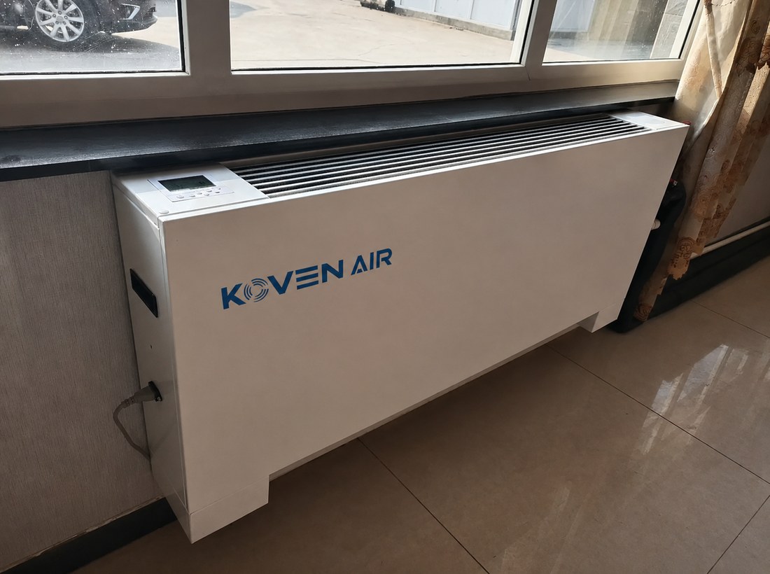
Cooling and Heating Without a Dropped Ceiling, the Under-Window Vertical FCU
A vertical fan coil unit draws room air in near the floor, passes it across a hot- or chilled-water coil, and discharges the conditioned air upward into the room. It carries no compressor and no refrigerant circuit of its own; its hot or cool water supply comes from a central heating boiler or water chiller, meaning that the fan coil is technically a terminal, not plant equipment. In the floor-standing form this terminal stands openly within the room space, typically below the window behind a decorative cabinet.
Where this configuration is the wrong answer
Payette’s finding cuts both ways, and the honest reading matters more than the sales one: with a highly performing glazing assembly, those downdraft and radiant penalties can come down so low that they entirely remove the need for supplemental perimeter heating. A new curtain-wall tower with a low U-factor build-up may no longer need anything below the window line. Floor-standing vertical fan coils are engineered to earn their position in the buildings that dominate the installed stock – standard glazing, high-rise apartments, hotel refurbishments, and residential floors with neither under-floor heating nor ceiling void space to work with – but if your facade already resolves the downdraft issues, state it up front and select a concealed or ceiling terminal instead.
SYS.01 // RANGE OVERVIEW
The KA-FP-WM Vertical Fan Coil Range, 9 Models and How to Select
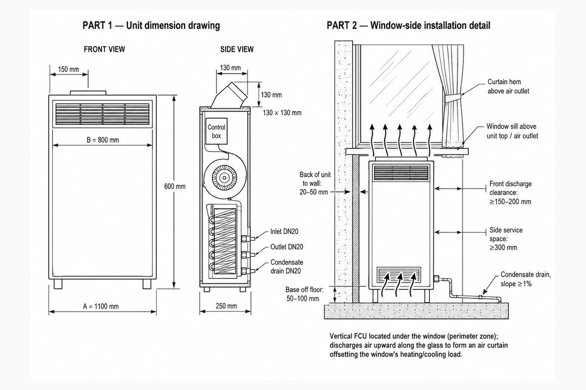
Every model in the range shares one cabinet envelope and one coil construction, and varies only in width and capacity. Height is fixed at 600 mm and depth at 250 mm across all nine models, so the unit clears a standard window sill and holds a shallow floor footprint.
Coil construction is copper tube with aluminium fins, 3 rows, rated to a maximum working pressure of 1.6 MPa. Water connections, supply, return and condensate, are DN20 throughout. Air is moved by a double-inlet forward-curved multi-blade centrifugal fan on an AC three-speed motor at 110 V or 220 V. Fan speed is a real control lever, not just a comfort setting — patented heating-system control schemes turn on adjusting exactly this (EP4624817A1).
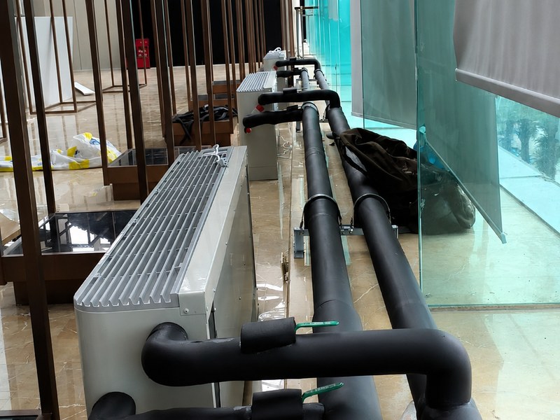
VIS.01 // SCHEMATIC VIEW
DOC.02 // SELECTION DOCTRINE
Sizing and Selection Doctrine
To read from the top down is the wrong way to select. Selection begins from the room load, and the trap is capacity, not shortage. If you oversize a hydronic fan coil, it will achieve setpoint before it has removed the moisture from the air and will short-cycle – since the coil never runs long enough at the correct surface temperature to condense water from the airstream – and the result is fluctuating temperatures and high humidity.
The motor and valve get excess wear because the equipment was never designed for it. Practitioners explain this using language a catalog would never dare to use: “the equipment is often bad at dehumidifying at part load conditions. With oversizing you make it worse, a lot more short cycling”.
Design engineers have reached the same conclusion from the opposite end: oversizing the system will result in more short-cycling, poor dehumidification, and wasted energy to overcome it. KOVEN AIR engineers keep this margin down to 10-15% and their 1.6 MPa coil was designed with the same ethos: correct sized, and pressure-tested at 1.5× working pressure, not padded.
“We size to the calculated load with a 10 to 15 percent margin, not a model size up. When a room fights us, the answer is almost always external static pressure and air distribution, not more coil. A unit that is one size too big will pass its factory test and still make the room uncomfortable.”
DAT.03 // TECHNICAL MATRICES
| Model | Airflow H/M/L (m³/h) | Cooling, high (W) | Heating, high (W) | Chilled water (kg/h) | Input power (W) | Sound dB(A) | Weight (kg) | Cabinet width (mm) |
|---|---|---|---|---|---|---|---|---|
| KAFP-02 | 340 / 246 / 161 | 2,250 | 3,404 | 390 | 36 / 43 / 48 | 37 / 40 / 42 | 21 | 745 |
| KAFP-03 | 510 / 375 / 254 | 3,320 | 5,005 | 570 | 50 / 57 / 64 | 39 / 42 / 44 | 30 | 900 |
| KAFP-04 | 680 / 508 / 345 | 4,396 | 6,512 | 760 | 60 / 70 / 81 | 41 / 44 / 46 | 32 | 1,000 |
| KAFP-05 | 850 / 654 / 415 | 5,135 | 7,703 | 880 | 74 / 84 / 97 | 43 / 46 / 47 | 35.5 | 1,100 |
| KAFP-06 | 1,020 / 775 / 516 | 6,188 | 9,187 | 1,060 | 93 / 105 / 114 | 45 / 47 / 49 | 40 | 1,230 |
| KAFP-08 | 1,360 / 1,034 / 684 | 8,293 | 12,414 | 1,430 | 130 / 151 / 169 | 46 / 48 / 50 | 59 | 1,500 |
| KAFP-10 | 1,700 / 1,293 / 877 | 9,557 | 14,440 | 1,640 | 147 / 169 / 204 | 46 / 48 / 50 | 63 | 1,700 |
| KAFP-12 | 2,040 / 1,565 / 1,038 | 10,888 | 17,321 | 1,870 | 183 / 206 / 243 | 50 / 52 / 54 | 69 | 1,900 |
| KAFP-14 | 2,380 / 1,895 / 1,204 | 13,529 | 20,187 | 2,330 | 221 / 245 / 291 | 52 / 54 / 56 | 76 | 2,100 |
Series nominal ratings. Heating figures are at 60 °C entering water; 45 °C low-temperature water is also a working condition, at reduced output. Height 600 mm, depth 250 mm, side discharge 130 × 130 mm and DN20 connections are common to all nine models. Water-side resistance runs 30–50 kPa depending on model. Allow 50–100 mm under the base for levelling feet, 20–50 mm at the back for pipework and return air, and ≥300 mm at the service side. At low speed the smaller models run at 37–41 dB(A), quiet enough for a bedroom at night. Pipe configuration changes coil circuiting and therefore output — see the 2-pipe and 4-pipe section below, and request a selection calculation for the configuration you intend to build.
For the residential project, the doctrine dictated a per-room, rather than per-apartment, selection. Each 120 m² three-bedroom apartment received four terminals sized to the actual room, not four identical machines.
| Room | Model selected | Airflow, high (m³/h) | Cooling (kW) | Heating (kW) | Units per apartment |
|---|---|---|---|---|---|
| Living room | KA-FP-06WM | 1,020 | 6.19 | 9.19 | 1 |
| Master bedroom | KA-FP-05WM | 850 | 5.14 | 7.70 | 1 |
| Second bedroom | KA-FP-05WM | 850 | 5.14 | 7.70 | 1 |
| Study | KA-FP-03WM | 510 | 3.32 | 5.00 | 1 |
| Apartment total | 4 terminals | — | ≈19.8 | ≈29.6 | 4 |
Selection from the 32-story, 128-apartment building. Chilled water 7/12 °C; heating water 60 °C or 45 °C entering.
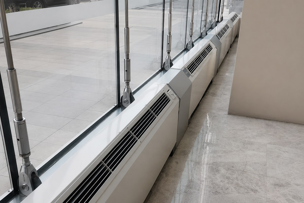
Vertical FCU Types, Floor-Standing Exposed vs Stack vs Concealed
“Vertical fan coil unit” covers three products that share an airflow direction and almost nothing else. Specifying the wrong one is the site-coordination error that most often forces a terminal schedule to be reissued. All three split on where the unit lives and who can reach it after occupancy — and only one of them is a blow-through cabinet that stands in the room.
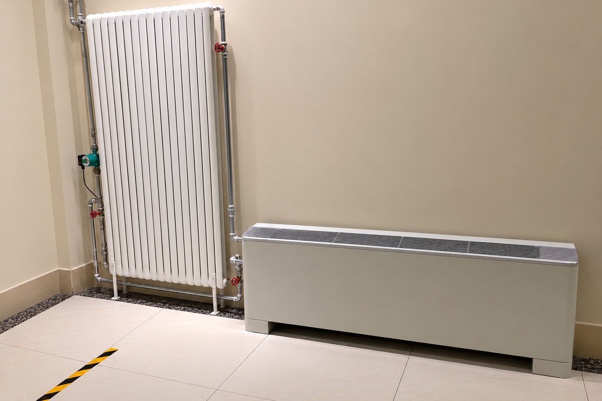
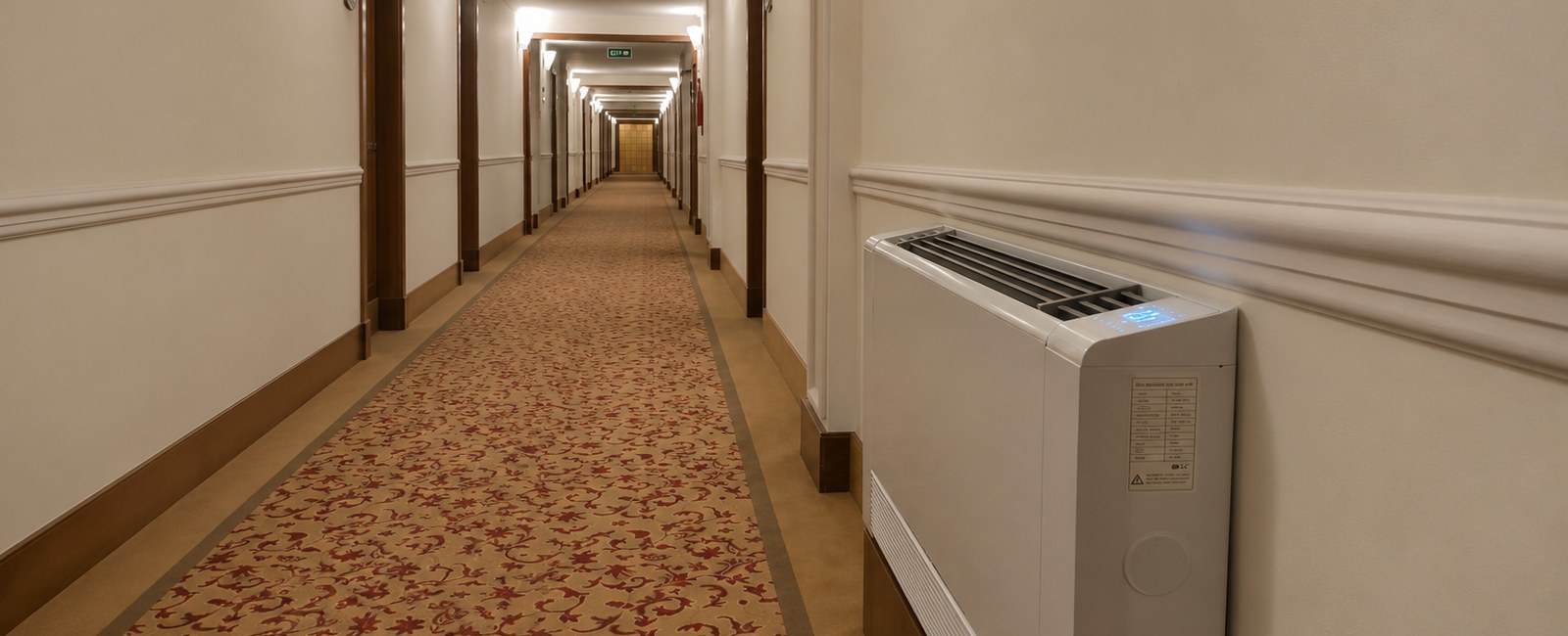
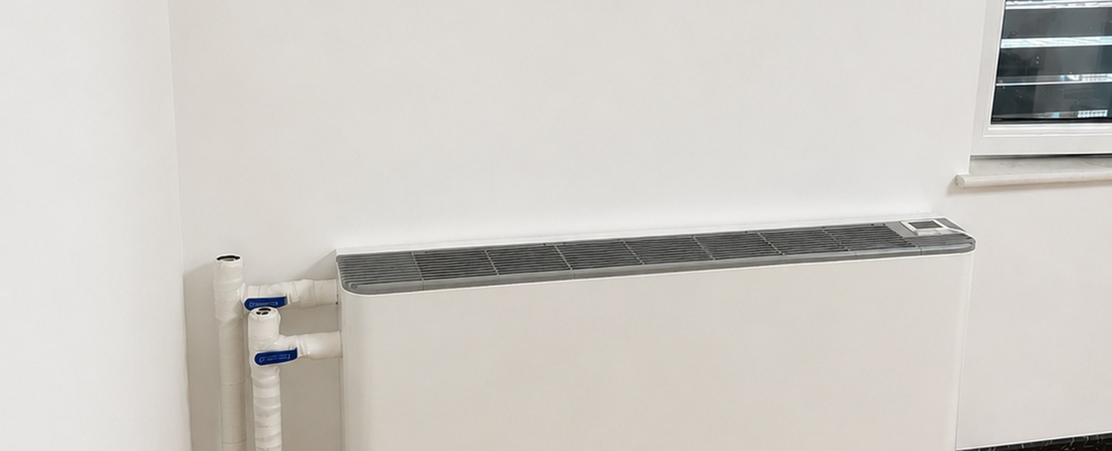
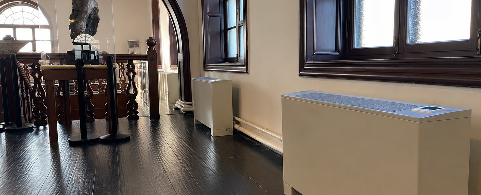
A floor-standing exposed fan coil unit is designed to be seen, which is exactly why it can also be reached. The vertical cabinet is a distinct machine in the patent literature too, not a horizontal unit stood on end US8939826B2.
The Vertical FCU Type Selector
| Location | In the room, on the floor, under the window |
|---|---|
| Risers | None — branch off the floor’s own pipework |
| Ceiling void needed | 0 mm |
| Floor footprint | 250 mm deep × 745–2,100 mm wide |
| Filter and coil access | From inside the room, no demolition |
| Best fit | Existing high-rise apartments, hotel refurbishment, floors with no ceiling void and no floor heating |
| Where it loses | Occupies visible wall length under the window |
| Location | Inside a wall cavity or closet, stacked floor to floor |
|---|---|
| Risers | Integral risers pass through the slab, one common riser serves the column |
| Ceiling void needed | 0 mm |
| Floor footprint | Wall cavity depth |
| Filter and coil access | Through an access panel in the wall |
| Best fit | New high-rise where a common riser saves installed cost across many identical floors |
| Where it loses | Riser coordination is fixed at design stage; retrofit is disruptive |
| Location | Inside a bulkhead, wall or closet; grilles only |
|---|---|
| Risers | None — branch connection |
| Ceiling void needed | Bulkhead or closet depth required |
| Floor footprint | Concealed volume |
| Filter and coil access | Through an access panel; may require ceiling or bulkhead removal |
| Best fit | Rooms where the terminal must be invisible and a service route exists |
| Where it loses | Service access depends on someone else’s finishes |
Service Path & Maintenance Reality
KOVEN AIR produces the first column. There’s a purpose for that limit and it highlights a true, seldom advertised feature for this class of product – the service path. Chilled water terminals get dirty. Every speck of dust that passes through the filter finds a home on a moist coil face. You may ask your service tech about a ten year old condo fan coil, and the verdict is rarely “replace it” — “They all look like that after many years. Could use a good cleaning but don’t replace what’s not broken.” That advice only helps if a technician can actually reach the coil. With floor standing exposed units, you can simply pop the front panel off inside the occupied space. You can access the coil, filter, drain pan and all the piping. No floor finish is removed, and nothing that sits on a ceiling has to be removed and replaced. With stack and concealed units, the exact same maintenance process requires the building to be in a state of construction – the phantom cost never on the sheet.
The honest counterweight: in a new building with dozens of near-identical stacked floors, a vertical stack fan coil unit shares one riser and shaves a lot of pipework and installation effort off the overall cost — arithmetic our floor-standing cabinet cannot compete with. Specify by building, not by preference. When you are weighing a vertical fan coil unit replacement in an occupied building, the access question normally comes to the fore well before capacity does.
Retrofitting an occupied floor?
Grab the 9-model spec sheet (PDF) & compare the cabinet to your sill height →2-Pipe vs 4-Pipe Vertical Fan Coils, Which System Fits Your Building
01 System Architecture
The number of pipes is a plant-level decision that lands on the terminal — enough of one that chilled-water fan coil circuiting has its own patented optimisation schemes (US20140242899A1). A 2-pipe fan coil has a single coil and a single supply and return piping circuit to it – either the entire building is running chilled water or hot water, and you change that over from plant-wide, on a seasonal basis.
A 4-pipe fan coil has the main cooling coil, but then also has a second, much smaller coil for heating with its own dedicated supply and return to that coil, so any room can request heat and the room next door can request cooling, any day of the year.
02 The Hidden Trade-off
Most of the KA-FP-WM units we ship are 2-pipe vertical fan coil units and so the difference between the two types of system design is something worth nailing down before we’ve developed your model schedule.
This is where the trade-off is made that gets overlooked and it lies in the heating output. In a 2-pipe device, the heating water flows through all three rows of the coil and hence has a high heating output. In a 4-pipe device, heating comes from a dedicated additional coil — a 3+1 row arrangement, which generates far less heat because it’s designed to re-heat air for dehumidification, not a full heating design load on its own.
03 Data Evidence & Risks
Using KAFP-05WA pairs, KOVEN AIR technicians measured 60°C entering water on both systems, yielding 7,425 W of heating output for the 2-pipe system compared to just 3,127 W from the 4-pipe system’s heating coil alone (42% of the 2-pipe unit) while cooling output was roughly comparable (4,950 W for 2-pipe, 5,135 W for 4-pipe).
That’s the mistake worth naming.
Specify 4-pipe “because it’s better,” then experience a heating deficit in a cold-climate perimeter room following hand-off, and fixing it costs a bundle — the coil is inside a cabinet that’s already been installed, piped, valved and commissioned. Cooling capacity is not where the two configurations diverge. Heating is — and only one of them tells you so before the order.
The Decision Grid Specifications
Coil arrangement
2-pipe
3 rows, single coil
4-pipe
3 + 1 rows, dedicated coil
Pipes at the terminal
2-pipe
2 (supply + return)
4-pipe
4 (chilled S/R + hot S/R)
Unit weight (kg)
2-pipe
18
4-pipe
22
Valves per terminal
2-pipe
1 two-way or three-way
4-pipe
2, plus interlock control
Cooling, KAFP-05WA basis (W)
2-pipe
4,950
4-pipe
5,135
Heating, KAFP-05WA basis (W)
2-pipe
7,425
4-pipe
3,127
Hot water flow (kg/h)
2-pipe
Shares the chilled circuit
4-pipe
270, independent circuit
Input power at 50 Pa (W)
2-pipe
97
4-pipe
100
Simultaneous heating and cooling
2-pipe
Not possible — 1 mode at a time
4-pipe
Any zone, any day, no changeover
Independent humidity control
2-pipe
Not possible
4-pipe
Yes — subcool then reheat
Shoulder-season behaviour
2-pipe
Locked to plant’s current mode
4-pipe
Follows the zone (no waste)
First cost
2-pipe
Lower
4-pipe
Higher — roughly double the pipework, plus coil, valves and controls
Best fit environments
2-pipe
Residential, budget-led projects, single-season load profiles, mild climates
4-pipe
Hospitals and operating suites, laboratories, five-star hotels, core & perimeter
Working figures represent the KAFP-05WA measured config pair from KOVEN AIR comparison workbook. Air flow & Fan are the same between configs; the change is the coil and circuit. Design resources are ASHRAE Handbook- HVAC Systems & Equip(fan-coil chapter) and ASHRAE Std 90.1.
One question decides it
Does this building require both rooms to operate at different modes simultaneously at any given hour, on any given day? If yes-e.g., a hospital wing, office core vs. glazed exterior, a lab-the 4-pipe premium offers value, and the heating deficiency associated with the dedicated coil should be planned for, not found. If no-e.g., apartment building, low-cost hotel, moderate climate-the 2-pipe system provides greater heat output per terminal, fewer valves for commissioning, fewer joints for potential leaks, and a lower overall cost. Our residential project on this page utilized 2-pipe for precisely this reason.
Still unsure about what configuration will suit your plant?
Please provide your design conditions and we can prepare an engineering estimate →Proven in the Field, a 512-Unit High-Rise and a 420-Unit Hotel
Replacement cost is the risk that makes building owners nervous of terminal units, and quite rightly so. A Toronto condo discussion thread summarises it in four words of title “Mandatory condo AC fan coil replacement costing over $10,000”, and the residents below aren’t discussing different brands, they’re taking an expensive hit one by one. This happens because terminal units are selected once at tender by someone who will not be there when it fails. A unit that’s specified once, and quietly operates for ten years is worth a lot more than any spec-sheet advantages. Here are KOVEN AIR’s two deployments against that benchmark.
32-storey residential tower,
512 floor-standing units
Hover to turn page
Technical Specifications
Building
32 floors, 128 apartments
Apartment type
3-bed / 2-living, ≈120 m²
Terminals
4 per apartment · 512 total
Cooling (Apt / Bldg)
≈19.8 kW / ≈2,530 kW
Heating, whole bldg
≈3,790 kW at 60 °C
Water Design
Chilled 7/12 °C · heat 60/45 °C
Room temp stability
within ±1.0 °C
Sound in service
37–56 dB(A)
The driver was constraint, not preference: low floor-to-floor height, apartment interiors finished without a ceiling void, no floor-level pipework provision for floor heating. One water system handles both seasons, with LCD thermostat control to each room, and the radiators that would otherwise have been needed were never installed.
180m mixed-use tower,
420 hotel fan coil units
Hover to turn page
Technical Specifications
Building
≈180 m, 38 fl; hotel + offices
Terminals
420 units, 2-pipe chilled/hot
Cooling range / unit
2.2–7.1 kW
Terminal cap., total
≈1,650 kW
Water design
7/12 °C (S) · 60/50 °C (W)
Sound target
≤ NR35 (≈35 dB(A))
First-pass accept
≥99%
Delivery
3 batches on schedule
A horizontal concealed, not floor-standing unit – shown here because it’s where the KOVEN AIR quality process was tested at scale: hydrostatic testing of every coil, balancing of every fan wheel, and a test run of every unit through all 3 speeds prior to dispatch.
Global Application History
Both are contained within a much wider history of installation. KOVEN AIR units operate in over 35 countries including, among many others, Brazil, the United States, Indonesia, Malaysia, South Africa and Mexico, with the company’s HVACR equipment installed for industrial and commercial operations such as Samsung Electronics, Tesla, BMW, Yadea, and Hilton. The application range for this type of terminal follows exactly the same principle in every case – rooms requiring individually controlled comfort, supplied by a central water plant. This is anywhere such comfort is required from hotel guest rooms, apartments and condominiums, data centres and computer rooms where fan coils sit in the cooling loop (US10785896B2), through offices, hospital patient rooms, gymnasiums, libraries and dormitories to the outer shell of buildings where heat loss to the glass is the dominant heat transfer.
QC Protocol // VFC Systems
Certifications, Testing and Quality Control
CE
European conformity marking
ISO 9001:2015
Quality management system
ISO 14001:2015
Environmental management system
ISO 45001:2018
Occupational health & safety
The honest version: what we hold, and what we do not
A submittal which has been thrown out at technical review is a costly delay and typically, the reason it has been rejected is due to a gap in certifications that nobody spotted at the enquiry stage. So here is the risk stated up front rather than discovered late. Fan coil published performance in the United States is based on AHRI Standard 440 (I-P) / 441 (SI), Performance Rating of Fan-coil Units, the current standard being 440-2019 (R2024). This standard defines what needs to be measured, how it should be measured, how to calculate performance ratings, the minimum required information for published ratings, operating conditions, and nameplate data. AHRI 440 is called out by ASHRAE 90.1 for performance rating because the energy code requires one accepted way to allow comparison between manufacturers’ published performance – precisely the reason a US specifier will write the standard number by name.
KOVEN AIR fan coil units aren’t listed on the AHRI directory – we wouldn’t claim a certification that we haven’t received. We have CE and the ISO 9001 / 14001 / 45001 management-system trio, and we rate our published performance from our own chiller and heat-pump testing laboratory, using the air-enthalpy method that calibrates capacity from measured inlet and outlet water temperature (CN202485915U). Should your specification insist on an AHRI certified terminal, you should know it on this page rather than at submittal review. What KOVEN AIR does put behind its numbers, however, is process and data access: 18 standardised production processes and 23 sheet-metal precision machining processes, feeding a modular line where intelligent robots assemble each unit; 400 points of traceability through manufacturing; 36 factory inspection tests; a 24-hour aging test; and a hydrostatic and air-tightness test at 1.5 × working pressure on every unit, not just a sample. Before any order, our engineers check your selection calculation against your design conditions and issue the supporting data for review — confirm it against your specification clause before you shortlist.
1.6 MPa
Coil maximum working pressure
1.5× test
Hydrostatic test, every unit
24-hour
Aging test
36 checks
Factory inspection points
Customization, Lead Time and After-Sales Support
There are only two things that determine fan coil price in this model series, and it isn’t the model number per se. The first is configuration: number of pipe circuit; rows of coil; size of cabinet and type of finish; the specification of the fan motor; provision for control valve and thermostat; whether a piping kit leaves the factory with the fan coil. The second factor is the project “shape”; quantity and batch delivery to the site according to the main contractor’s floor sequencing plan; and the amount of design effort behind the supply. It doesn’t make sense to provide catalogue prices because no two projects are identical – you can’t supply the same unit for a 2 pipe, 745mm fan coil cabinet and a 4 pipe, 2,100mm fan coil cabinet.
Cost and lead-time driver
Explore the primary factors that move pricing and scheduling for custom fan coil units.
Cost / Lead-time driver
What moves it
Pipe configuration
4-pipe adds a coil, a second circuit, a second valve and sequencing control against 2-pipe
Model size and qty
Cabinet width 745–2,100 mm; batch sizes change the production schedule, not just the unit rate
Motor specification
Standard AC three-speed, or a built-to-order alternative where a specification demands it
Controls & valve package
Unit LCD thermostat as standard; two-way or three-way valves, actuators, and BMS interface on request — most of the configuration flexibility sits here
Cabinet finish
Standard white powder coat; project-specific finishes on request
Delivery sequencing
Batched to the construction programme rather than in one shipment
Engineering scope
Selection calculation, CAD/BIM files, performance curves, control logic, wiring diagrams, installation manual
Our service commitment
Our service commitment runs in three stages, the middle stage is typically the point where terminal projects often fall apart. Prior to ordering, our engineers will check the accuracy of your project parameters against your project design and provide the calculation.
When delivering, units ship only after production testing by our engineers who will then attend site to install and commission, adapting to the conditions actually present on site.
After handover, technical service guidance is free for the life of the equipment. During warranty period all defects are handled with minimum of delay, and we operate periodic training courses for the contractors and engineers that will eventually service the units. An 18 month unit warranty is provided with every unit supplied.
Terminal-unit contract
Two things to write into your terminal-unit contract:
First, a damage-reporting window. Standard industry practice for fan coil unit (FCU) installation and commissioning is to test all fan coils with the driver before acceptance into storage and submit written damage claims to the manufacturer with accompanying photographs, normally within 3 days. The acceptable timeframe for this reporting window should be agreed before the first batch is delivered to site.
Second, condensate. Drain-pan and overflow design is patented engineering in its own right (EP0714003A2), which tells you how often it goes wrong. This is reported in engineering trade journals as being the single most overlooked design/installation component of the fan coil unit and rarely specified adequately, if at all in the contract documents.
Our rule of thumb at a recent hotel installation is simple: at least 1% continuously sloped drainage to the drain, flex pipe connections and full vapour-sealed insulation on every cool surface. Slope to drain, flex to stop noise, seal to stop sweat. Miss any of these and it will be a call out.
Vertical Fan Coil Unit Engineering Tools
01
Vertical Fan Coil Model Selector
Enter the calculated room load and this returns the KA-FP-WM model that carries it with a 10–15% margin — the sizing rule our engineers work to. It will not round you up a size.
02
2-Pipe vs 4-Pipe Decision Grid
Six questions. The answer usually turns on one of them — whether two rooms need opposite modes at the same hour. The tool also shows the heating trade-off that gets discovered too late.
03
Under-Window Fit Check
The cabinet is 600 mm high and 250 mm deep on every model — only the width changes. This checks a chosen model against your sill, your wall run and the clearances the unit needs to be serviceable later.
FAQ: Specifying Vertical Fan Coil Units
No. It recirculates room air and passes it over a water coil. outdoor air should be handled separately by a design that sits alongside, rather than after, the fan coil schedule.
Yes, on a single water circuit. One coil takes hot water at 60 °C, or low-temp water at 45 °C, and cold water at 7/12 °C in summer. Our KA-FP-05WM delivers 5,135 W cooling and 7,703 W heating at high fan speed. With a 2 pipe system, temperature is switched at the plant, thus entire building remains in one mode.
Scale and duty. A fan coil is a terminal that serves one room or zone and is sized in kilowatts and it typically doesn’t require duct work. Air handling units, however, serve the entire building or large spaces and they use duct work for air distribution and typically provide for the outdoor air load.
Each unit ships with its own LCD thermostat for local temperature, speed and timer control which is what the residential project used. Integrators are right to ask early – “most fan coil unit manufacturers support Modbus RS-485” is the working assumption on home-automation and BMS forums and it’s worth confirming rather than assuming. On this series, RS-485 / Modbus and BMS interfacing is a controls-package question rather than a standard catalogue line; send us the points list and control philosophy for your project and we’ll confirm in writing what the unit and valve package will support before you specify it.
Let the building decide, in this order. Firstly, is there a ceiling void or bulkhead deep enough to hide a unit in? No void and an existing building suggest floor-standing exposed. Secondly, is this new build with many repeating floors which could share one riser? That arithmetic favors a stack unit, and our floor-standing cabinet can’t beat it. Thirdly, who’s going to have to reach the filter and coil in year six and what will they have to cut open to do it? Exposed units answer that question best because everything opens from inside the room. A void with a clear service route suggests concealed. Most projects are decided by the first question alone.
It will foul – that’s normal, not a defect. Chilled-water coils collect whatever gets past the filter, and a decade-old unit in a residential building generally needs a clean rather than a replacement. Routine work includes filter cleaning or replacement on a schedule dictated by the space, a coil face clean, a drain pan and condensate line check before each cooling season and a valve and actuator check. Fouling matters mainly because of the cost of access: on a floor-standing exposed unit, the front panel comes off inside the room, and the filter, coil face, drain pan and water connections are all in front of the technician, so a clean is a single visit. On a concealed unit, the same job begins with someone’s ceiling. Budget for the access as much as the labor.
No. Our units are not listed in the AHRI directory. We hold CE and ISO 9001:2015, ISO 14001:2015 and ISO 45001:2018. We rate published performance from our own chiller and heat-pump testing laboratory, and each unit is hydrostatically tested at 1.5 times working pressure before shipment. If your specification demands AHRI 440, please tell us at enquiry so that we can address the issue rather than surprising you at submittal.
Calculate the room load, add 10-15%, then hold that line. Don’t up-size the model for reassurance. If a room resists, consider external static pressure and air distribution before adding coil.


![Commercial Rooftop Unit Guide: Types, Sizing & Costs [2026]](https://kovenair.com/wp-content/uploads/2026/07/commercial-rooftop-unit-guide-featured-2-150x150.png)