
Get in Touch with Koven Air Company


Updated July 2026.
A dry cooling coil is a chilled-water heat exchanger that conditions indoor air using sensible heat only, so no condensation ever forms on its surface — which is exactly what GMP process areas depend on it for. Get the water temperature, face velocity, or standards references wrong, and you either lose the “dry” behavior entirely or over-engineer for a contamination risk you never had. This guide covers what a dry cooling coil is, how it’s sized, which standards govern it, and where it fits into a broader HVAC system in a pharmaceutical GMP process area — the questions worth answering before requesting a quote.
Quick Specs
| Function | Sensible-heat-only cooling — no dehumidification |
| Typical chilled water temps | 13°C supply / 18°C return (industry convention, not a fixed standard) |
| Face velocity range | 0.6-2.5 m/s (2 m/s typical optimum) |
| Water velocity range | 0.8-1.8 m/s |
| Governing US regulation | 21 CFR 211.46 |
| Governing EU regulation | EU GMP Annex 1 (fully applicable since 25 August 2024) |
What Is a Dry Cooling Coil (DCC)?
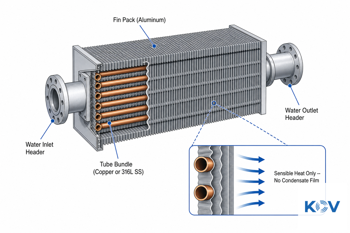
A dry cooling coil (DCC) is a chilled-water heat exchanger that removes heat from air using sensible cooling only, keeping its surface temperature above the room’s dew point so no condensation ever forms. Chilled water supply stays roughly 2°C above dew point, and the coil is asked to do the sensible-heat job only, never the latent one.
Most standard cooling coils, by contrast, run water cold enough to fall below the entering air’s dew point — that’s how they dehumidify, but it’s also why they need a condensate drain, and why a poorly maintained drain pan becomes a microbial growth site. A DCC skips that step entirely.
At its core, a DCC is a heat exchange device. Chilled water flows through a series of tubes, and a fan blows room air over the fins. Heat transfers from the hotter air to the cooler water, and no refrigerant undergoes any state change within the coil. Across the available manufacturers’ material (vrcoolertech.com and sz-pharma.com) which publish this information, the same water temperature is consistently used: 13°C for the supply water, and 18°C for the return water. There’s no engineering standard listed behind these numbers; it’s more of an industry convention driven by converged design experience. However, the physics is there and supported in academia. For example, the Purdue ME 418 cooling coil design course notes states: in a completely dry coil, “the air-side surface temperature is above entering air dew point and as a direct result condensation doesn’t occur in the coil.” It’s that simple; if the coldest surface is kept above the room’s dew point temperature, no moisture can condense.
💡 The 2-Degree Dew-Point Margin Rule
Three independent design references-two competitive manufacturers and the ASHRAE 90.1 energy-code minimum for chilled-water coil selection (up.codes, cross-verified against Trane’s own ASHRAE 90.1 engineering newsletter)-converge on the same underlying margin. Both manufacturers’ 13°C/18°C convention sits about 2°C above a typical indoor dew point. ASHRAE 90.1’s energy-efficiency requirement is commonly cited in secondary engineering references-including up.codes and Trane’s own ASHRAE 90.1 engineering newsletter, independently-as calling for at least a 15°F (8.3°C) temperature difference between the coil’s leaving and entering water. That’s a different regulatory rationale (minimum efficiency, not GMP contamination control) that happens to land in the same neighborhood; if you need the number for a validation document, pull it from the actual ASHRAE 90.1 standard rather than a secondary summary, this one included. Neither source cites the other. That’s not a coincidence you’ll find written down anywhere as a named rule-it’s what happens when three separate design traditions independently arrive at “enough margin to survive normal sensor drift and humidity swings, not so much that you lose capacity.” Use it as a sanity check on any DCC sizing proposal: if your quoted inlet water temperature is within 1°C of your room’s design dew point, ask why-that margin is what prevents condensation from forming in the first place, and it’s not a place to cut corners just to squeeze out more rated cooling capacity.
None of this is a claim that GMP process areas are somehow more dust-sensitive than a comfort-cooling application-cleanliness classification runs on filtration and air changes, not coil type. What sensible-only cooling buys a GMP facility is the elimination of a specific, well-documented microbial risk: standing condensate. Koven Air’s pharmaceutical dry cooling coil line is built around that exact requirement for GMP process areas, with sizing worked out against a specific facility’s cooling load rather than a generic catalog spec.
Dry Coil vs. Wet Coil: Sensible Heat vs. Latent Heat, Explained
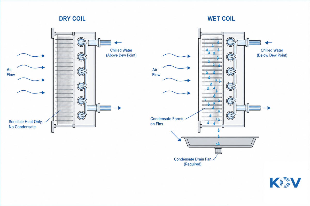
A practitioner thread on hvac-Talk puts the distinction about as plainly as it gets: “A dry cooling coil removes sensible heat from the air stream. A wet coil removes sensible and latent heat (moisture) from the air stream.” That’s the whole difference in one sentence-a wet coil does two jobs, a dry coil does one. Purdue’s ME 418 coil design coursework formalizes the same split into “totally dry,” “totally wet,” and “partially dry/partially wet” coil operating regimes, which is the more precise engineering language behind the practitioner shorthand.
| Coil Type / Parameter | Dry Coil (DCC) | Wet (Standard) Coil |
|---|---|---|
| Load handled | Sensible only | Sensible + latent |
| Chilled water supply temp | Above room dew point (~13°C typical) | Below room dew point (~5-7°C typical) |
| Condensate drain required | No (but a drain pan is still recommended for high-humidity upset conditions) | Yes, always |
| Humidity control | None — must be handled upstream (typically by a make-up air unit) | Built in |
| Microbial growth risk from standing condensate | Eliminated at the coil | Managed via drain pan maintenance |
| Typical face velocity | 0.6-2.5 m/s (2 m/s optimum) | 1.5-3.0 m/s typical |
| Typical water velocity | 0.8-1.8 m/s | 1.0-2.4 m/s |
| Air-side pressure drop (uncited manufacturer parameter, >3 fin rows at high face velocity) | Manufacturers cite >30 Pa as the threshold to design against | Typically higher due to wetted-surface drag |
| Best-fit application | GMP process areas, semiconductor cleanrooms, precision electronics | General comfort cooling, spaces needing active dehumidification |
| Retrofit complexity into an existing AHU | Requires confirmed upstream humidity control (see FAQ) | Drop-in for most standard AHU cabinets |
The tradeoff is straightforward: a dry coil can’t dehumidify, so it only ever works as part of a system where something else-usually a make-up air unit-is already carrying the latent heat load and providing temperature and humidity control on the incoming air. Bolt a DCC onto a space with no separate humidity control and you’ll hold temperature fine while relative humidity drifts wherever the process load take it. Heat removal at the coil itself is unaffected either way-inlet and outlet water temperatures determine sensible capacity regardless of what’s happening with moisture upstream.
Why Dry Coils Matter for Condensation Control in GMP Process Areas
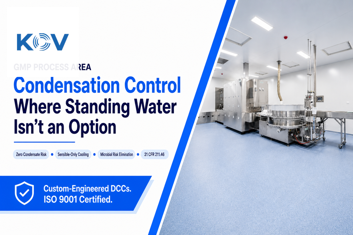
Dry coils matter because U.S. federal regulation ties ventilation equipment directly to contamination control: 21 CFR 211.46 requires “equipment for adequate control over air pressure, micro-organisms, dust, humidity, and temperature.” Micro-organisms and humidity sit in the same clause as temperature and pressure — condensation-driven microbial risk is a primary HVAC design concern, not a peripheral one.
“A cooling coil cools (sensible) and dehumidifies (latent) an air stream… a totally dry coil’s air-side surface temperature stays above the entering air dew point, so condensation does not occur in the coil.”
Adapted from Purdue University ME 418, Cooling Coil Analysis & Design (2024 course notes)
On the EU side, the regulation is EU GMP Annex 1, which came into full effect on 25 August 2024. It places contamination control strategy rather than a point-in-time cleanliness classification at the center of sterile manufacturing facility design. A wet coil in a return-air plenum with a fouled or overflowing drain pan represents the sort of latent contamination that a documented Contamination Control Strategy (CCS) is intended to identify before any inspectors do. A dry coil won’t remove the need for a CCS, but it eliminates one possible mode of failure: the coil doesn’t contain standing water where anything can grow.
Picture the failure mode this actually prevents: a return-air plenum wet coil running at a normal 6°C supply temperature, a drain pan that’s been dry-checked but not physically inspected in months, and a summer humidity spike that pushes condensate volume past what the pan’s slope was sized to handle. Two weeks later, an environmental monitoring swab from that plenum comes back with a microbial count above the alert limit, and the investigation traces it to standing water nobody was watching. That investigation isn’t made impossible by a dry coil, but the water it would have been looking for simply isn’t there.
What a dry coil is not: it’s worth being precise here. ISO 14644-1, the cleanroom classification standard, covers only the airborne particle count, not the microbial contamination level at all. DCC’s only relate to one method of contamination-condensation and liquid-and do not address your particle count, your filtration tier or your ISO classification. Those decisions involve other standards and are a common enough point of confusion to warrant a bold declaration: Changing your coil type does not change your cleanroom class, and vice versa.
How to Size a Dry Cooling Coil, The Sensible Heat Calculation, With a Worked Example
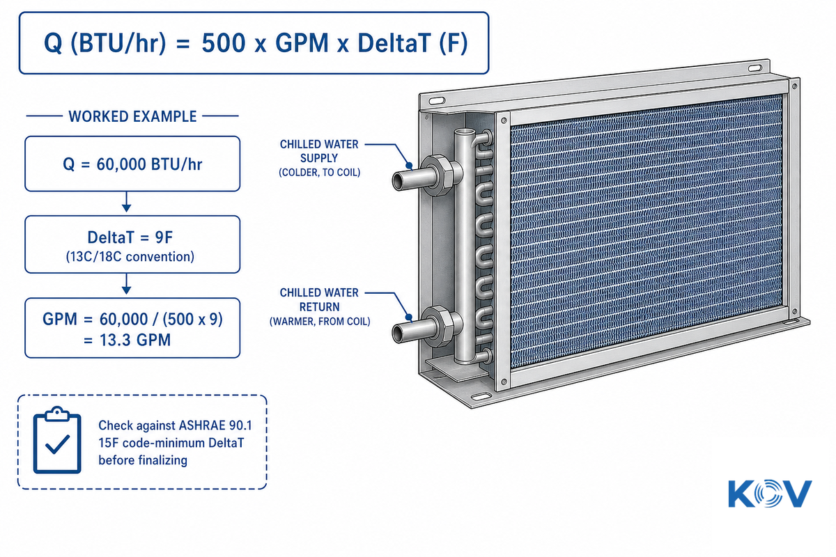
Water-side sensible heat, used in all hvac engineering applications, is frequently summarized by the following “rule of 500”:
📐 Engineering Note
Q (BTU/hr) = 500 × GPM × ΔT (°F)
The “500” is derived from water’s properties: 8.33 lb/gallon × 60 min/hour × 1.0 BTU/lb-F (water’s specific heat) = 500. Rather than accepting one supplier’s number as gospel, you can independently verify the 500 figure by consulting the properties of water.
Sample calculation: If a GMP process area has a calculated sensible heat load of 60,000 BTU/hr (approx. 17.6 kW) and the DCC operates according to the 13°C/18°C (55.4°F/64.4°F) standard mentioned previously (9°F or 5°C water-side ΔT):
Step-by-Step
- Use the formula to solve for GPM: GPM = Q/(500 × ΔT)
- Substitute the numbers into the equation: GPM = 60,000 / (500 × 9) = 60,000 / 4500
- Result: GPM ≈ 13.3
- Double check against the energy code minimum: ASHRAE 90.1’s chilled-water coil selection criteria requires a minimum 15°F (8.3°C) ΔT. A 9°F design ΔT is well below this efficiency-code floor – which, in practice means the water-side ΔT either has to be widened (tolerating a warmer return temperature), or the flow rate computed above should be re-checked against a vendor’s actual coil selection, rather than simply relying on the simplified formula.
That last step is one that’s almost universally omitted by competing specification sheets – of the manufacturer pages reviewed, none reference the code-minimum temperature difference even as much as a fleeting thought, let alone reconciliation with the quoted chilled water temperature convention. Rows of tubes, fin spacing, and face area will ultimately have far greater influence on actual heat transfer efficiency than the simplified formula alone; that’s why the formula serves as a sanity check rather than a direct substitute for a true coil selection. A 5°C water-side swing (9°F) is common place within cleanroom DCC marketing materials but by itself it fails to meet the 15°F code floor – a deficit a vendor’s actual coil selection tool should be overcoming using real fin geometry and row counts rather than an off-the-cuff GPM number. Use the simplified formula above to sanity check a proposal’s ball-park GPM value; don’t use it to replace a coil selection.
Heat Load Band → Typical Water Flow Reference
| Sensible Load | Approx. Flow @ 9°F ΔT | Typical Application Scale |
|---|---|---|
| 20,000-40,000 BTU/hr | 4.4-8.9 GPM | Single small process room |
| 40,000-100,000 BTU/hr | 8.9-22.2 GPM | Mid-size fill-finish or process suite |
| 100,000+ BTU/hr | 22.2+ GPM | Multi-zone process area, likely multiple coils |
Reference values only – true coil selection requires row counts, fin geometry, and face area.
Which Standards Govern Dry Coil Use in GMP HVAC?

Three separate regulatory frameworks apply to a GMP process area’s dry cooling coil: EU GMP Annex 1 governs contamination control strategy for sterile manufacturing, 21 CFR 211.46/211.67 cover U.S. cGMP ventilation and equipment maintenance, and ISO 14644-1 classifies airborne particle counts only. Confusing these three is an easy way to cite the wrong one in a validation package — each answers a different regulatory question, not interchangeable versions of the same requirement.
EU GMP Annex 1
Contamination control strategy for sterile manufacturing. Fully applicable since 25 Aug 2024.
21 CFR 211.46 & 211.67
US cGMP ventilation/air control and equipment maintenance requirements.
ISO 14644-1
Airborne particle classification only — not a microbial or contamination-control standard.
The most general of the three, EU GMP Annex 1, was updated in 2022 and the EU’s own EudraLex index indicates “fully applicable since 25 August 2024” – a date more recent than most secondary compliance blogs which tend to highlight the 2023 transition start date for much of Annex 1, failing to mention the longer compliance timelines for other provisions. Cite the EudraLex page directly in any internal validation documentation.
The US equivalent for any facility that markets to American clients is 21 CFR 211.46: “Adequate ventilation shall be provided.” It requires “equipment for adequate control over air pressure, micro-organisms, dust, humidity, and temperature” where it “may be appropriate.” No specific coil type (dry, wet or otherwise) is mandated, but a DCC is a reasonable and documentable choice for meeting the humidity/micro-organism control criteria of a process area that has a clearly defined sensible load.
The ISO 14644-1 controls cleanroom particle classification ( ISO Class 5 to 9) and-as we established above-is explicitly not intended for classification of viable particles or micro-organisms. For justifications of micro-organism control within a process area, a facility engineer specifying a DCC should reference either Annex 1 or 21 CFR 211.46. In the field, this mix-up shows up most often in validation packages where an engineer cites an ISO 14644-1 class certificate as evidence of contamination control — an auditor who knows the standard’s actual scope will flag that citation on the spot, and the resulting finding is an easy, avoidable one.
Material, Airflow Direction, and Where a Dry Coil Sits in Your AHU
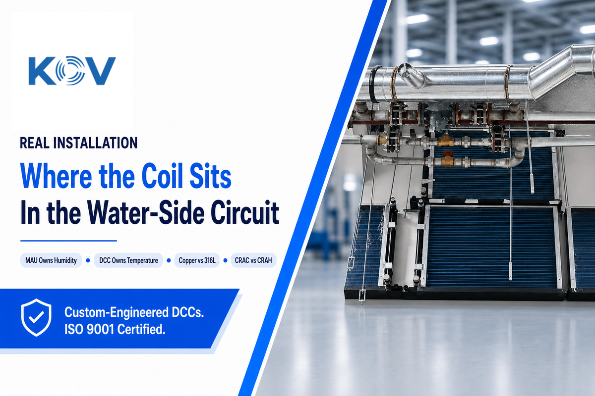
DCCs rarely work in isolation as a stand-alone air conditioning system. Most GMP process-area arrangements link three devices in a larger cleanroom air conditioning system with clearly defined functions: make-up air unit (MAU) for treatment and dehumidification of outdoor air before it enters the space, fan filter unit (FFU) to ensure particle cleanliness with continuous HEPA/ULPA filtering, and the dry cooling coil which handles temperature control exclusively — running off its own water circuit, independent of the MAU’s air-side treatment path. The MAU “owns” humidity; the DCC “owns” temperature.
They don’t conflict-and that’s precisely why you decouple sensible and latent control in the first place; in a combined wet coil, they would fight over the same water temperature setpoint.
Is the Indoor Unit a CRAC or CRAH Unit?
A CRAC (Computer Room Air Conditioner) is refrigeration-based, built around a direct-expansion (DX) evaporator coil. A CRAH (Computer Room Air Handler) instead uses a chilled-water coil piped from a central plant — this is where the DCC described in this guide actually lives.
The CRAC-versus-CRAH distinction confuses many first-time cleanroom cooling specifiers, and its own direct control valve setup makes CRAC a standalone mechanical cooling system in a way a CRAH is not. If your facility runs a central chilled water loop rather than standalone DX units, you’re specifying a CRAH, and the dry coil discussion in this guide applies directly. (On DX units, the sensible/latent separation logic still holds, but the hardware looks different.)
Getting the CRAC/CRAH distinction wrong at the spec stage is a common and expensive mistake: a facility team that assumes a chilled-water DCC when the site actually runs standalone DX units ends up with a coil that has nowhere to connect, forcing a re-spec cycle that can add weeks to a project timeline. Material selection carries a similar risk profile. Copper has higher thermal conductivity, which lets a copper coil hit a given cooling capacity with a smaller footprint, but copper is well known to be vulnerable to chloride-driven pitting corrosion, while 316L’s molybdenum content is specifically what gives it better resistance to the chlorine-based cleaning agents common in GMP washdown protocols — which is exactly why 316L gets specified for those environments despite its higher material cost. That’s a corrosion-resistance tradeoff worth pricing out before committing to a material, not after installation.
Material selection-the debate over copper vs. 304/316L stainless steel-is a genuine design axis among cleanroom cooling solutions built around a DCC, affecting everything from corrosion resistance to thermal conductivity to cost, and warrants its own discussion. Manufacturer design guides commonly specify heat-exchange tube diameters above 12.7 mm with wall thickness over 0.45 mm as the construction baseline for a multi-year service life, with factory pressure testing held at 3-7 kg/cm² for a minimum of 48 hours before a coil ships — figures worth asking about on any quote regardless of which material you choose. For more details, see Koven Air’s cleanroom dry cooling coil guide and learn more about cleanroom AHUs for pharma and biotech here or our guide to commercial air handling units here.
Common Dry Cooling Coil Problems and How to Catch Them Early
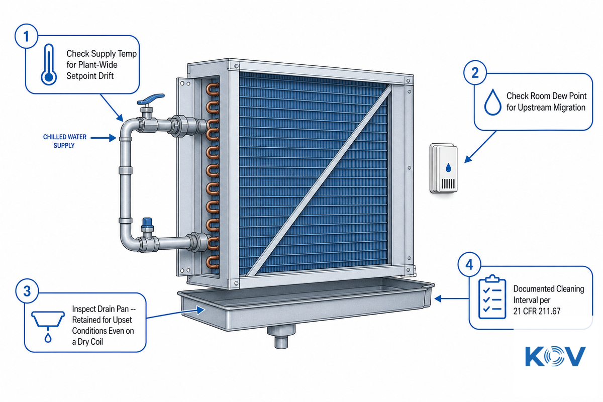
One of the most common practitioner forums observations is that DCC failures often manifest as problems elsewhere in the system, rather than as direct equipment failures. One hvac-Talk thread on dry-vs-wet coil issues and an r/HVAC Reddit thread on glycol-cooled dry coolers both suggest a common underlying failure pattern: dry coil that begins to produce condensate, and then the room is blamed before the coil is.
- When unanticipated moisture shows up, first check your chilled water supply temp; plant-wide setpoint fluctuations can force a DCC to push out lower supply temps without changing a single local setting.
- Double-check that the actual dew point in the room hasn’t migrated; a change upstream (more people, a new piece of equipment producing moisture, a MAU dehumidification fault) could push the dew point above the coil’s fixed supply temp even if the coil has done absolutely nothing at all.
- Inspect the drain pan, even on a coil that’s “supposed to” run dry. Both of the manufacturer design guides I’ve looked at for this piece state that the condensate drain pan should be retained for high-humidity upset conditions–treating a DCC as maintenance-free because it runs dry under normal conditions is a design assumption documented in the literature, not a guarantee.
- Follow a documented cleaning and inspection interval, regardless of condensate status. 21 CFR 211.67 requires equipment to be “cleaned, maintained, and, as appropriate for the nature of the drug, sanitized and/or sterilized at appropriate intervals” under written procedures; this includes the coil and its enclosure, regardless of whether it’s currently producing condensate.
None of this is unique to pharmaceutical GMP applications; this failure pattern can occur in any dry-coil setup, whether in data-center cooling or industrial process cooling. What changes in a GMP process area is the consequence: a wet-when-it-shouldn’t-be dry coil isn’t only an efficiency concern, it’s a documented deviation. Exact inspection intervals vary by facility risk classification and should come from your site’s own written maintenance procedures rather than a generic number — but whatever cadence your site already uses for coil-adjacent equipment (commonly a monthly visual check paired with a longer-interval teardown, per 21 CFR 211.67’s “appropriate intervals” language) is the cadence the DCC check belongs in, not a separate schedule invented just for this one component.
Industry Outlook, Where GMP Process Cooling Is Headed
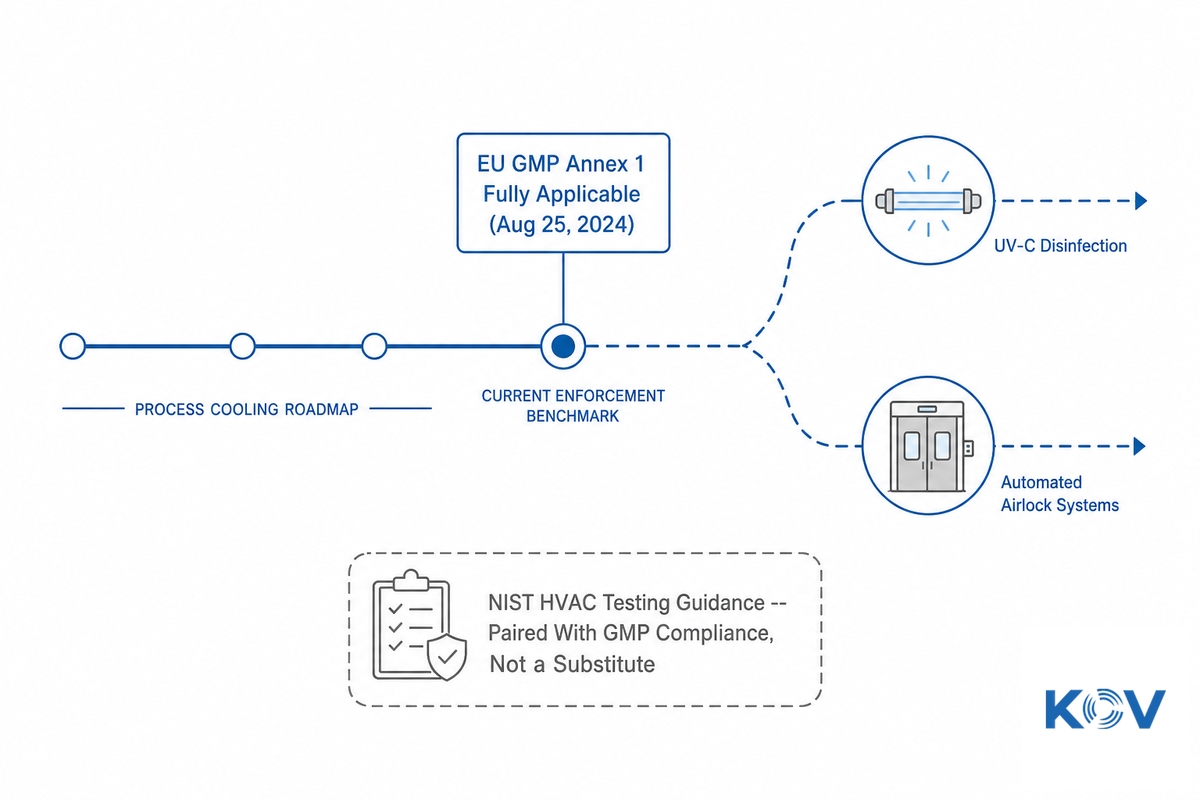
By far the most immediate and impactful driver for anyone currently specifying hvac for GMP process areas is that EU GMP Annex 1’s staggered implementation has concluded. The European Commission’s EudraLex page makes it official: the document, in its entirety-including its expanded focus on a documented Contamination Control Strategy-has been in effect since August 25, 2024, and serves as the current enforcement benchmark, not a future target. Companies that considered the 2023 compliance milestone to be the finish line and haven’t reassessed their CCS document against the currently effective Annex 1 regulations are working with outdated information. If your facility’s last formal CCS review predates August 2024, that document is now more than a year out of date against the standard it’s supposed to satisfy — worth a specific line item on next quarter’s validation calendar, not a someday task.
This regulatory maturation, not any specific market-size estimate, should be the primary factor influencing a facility engineer’s decision-making this year. Although market research indicates the overall cleanroom hvac compliance market will reach mid-single-digit-billion dollars with high-single-digit growth rates into the early 2030s-helpful for understanding the market’s overall growth trajectory and vendor landscape-this data is unlikely to dictate a particular product specification or standards application the way Annex 1’s new applicability does.
From a tech standpoint, a recent systematic literature review of cleanroom hvac research confirms that this area is a work in progress rather than a solved space, and industry trade coverage highlights UV-C disinfection, along with automated airlock systems, as the two clear tech trends that should see more attention in the next product cycle. On the general testing side, NIST’s HVAC functional inspection and testing guidance is the kind of baseline reference facility teams increasingly pair with GMP-specific rules rather than treating equipment testing and contamination-control compliance as separate tracks. Both work to remove microbial risks at the HVAC system, not downstream in the environmental monitoring alone-an approach dry cooling coil already takes with its condensation in relation to its system. Meanwhile, the parallel push towards free cooling in the wider industrial cooling space-a move that relies on favourable ambient conditions to save energy consumption and cut operating costs-is related but different from contamination control: a DCC’s role is restricted to controlling microbial contamination and a DCC’s impact shouldn’t be confused with general energy efficiency initiatives in the validation documents, doing so is an easy way to invite questions that you won’t have good answers for.
Frequently Asked Questions
Q: What is a dry cooling coil?
View Answer
A dry cooling coil is a chilled water supply system that provides cooling but does not produce condensation. It circulates water through its heat exchanger at temperatures high enough to keep it 2°C above room temperature-usually a 13°C supply and 18°C return temperature-allowing it to remove only sensible (temperature) heat, never latent (moisture) heat. The heat exchanger never cools to the point at which condensation occurs on the unit’s surfaces, eliminating a risk that a traditional wet heat exchanger instead manages using a condensate drain.
Q: How does dry cooling work?
View Answer
dry cooling relies on maintaining a uniform temperature for all surfaces with which air comes in contact at temperatures greater than room temperature. The heat exchanger circulates water through its dry cooling at supply temperatures higher than room temperature. Because no condensation occurs on the dry cooling surfaces, any water vapour present in the air remains as a vapour rather than condensing into a liquid form. A key characteristic is that it does not dehumidify the air; thus, humidity control is typically located at the makeup air unit.
Q: What is the difference between wet coil and dry coil?
View Answer
A wet coil cools air by removing sensible heat (temperature) and latent heat (moisture) together in a single pass, which means its chilled water runs cold enough to fall below the air’s dew point and produces condensate that has to go somewhere — hence the permanent condensate drain and drain pan. A dry coil, in contrast, removes only sensible heat: its water runs warmer than the dew point, so no condensation forms at the coil at all. The practical tradeoff is that a dry coil needs a separate humidity-control source elsewhere in the system (typically a make-up air unit), while a wet coil handles temperature and humidity together in one component, at the ongoing cost of managing condensate for the life of the equipment.
Q: When should AHU coils be replaced?
View Answer
No set time for replacement-replace upon detection of corrosion,airflow loss,or failure to maintain the set point at its rated capacity and rated air and water flow,during inspection,at documented inspection frequencies in accordance with 21 CFR 211.67, regardless of age.
Q: Can a dry cooling coil be retrofitted into an existing wet-coil AHU?
View Answer
Only physically, but only if you already have another way to control humidity; for example, a pre-existing make-up air unit with dehumidification capacity. Otherwise you’re just letting the humidity float freely in the space after you replace your wet coil with your dry coil, without first ensuring there’s a control point for humidity upstream of your DCC.
Q: Why are cleanrooms critical for pharmaceutical manufacturing quality?
View Answer
Cleanrooms exist to regulate variables that could negatively affect pharmaceutical product quality and patient safety: particulates in the air, pressure differentials that pull external contaminants inward, and – the issue a dry cooling coil solves directly – the potential for microbial growth due to standing moisture. Regulators treat these as inspection-relevant findings precisely because a facility that cannot control its own air cannot reliably control what ends up in the product. This is why hvac selection of equipment-and the type of coil selected-appears in regulatory documents like 21 CFR 211.46 and EU GMP Annex 1, and isn’t left solely as a decision for the mechanical engineer.
Q: What is hybrid cooling, and is it the same as a dry cooling coil?
View Answer
No – although they’re related concepts, they are not the same. Hybrid cooling refers to the practice of combining dry air-based (air-cooled) heat rejection and wet evaporative heat rejection at the cooling tower or dry cooler level and modulating between modes depending on the ambient conditions to balance water consumption against energy efficiency. In contrast, a dry cooling coil is specifically a chilled-water coil that goes inside an air handling unit to remove sensible heat, thereby preventing condensation in the conditioned space. A facility can run hybrid cooling in its central plant while also feeding a completely dry (non-hybrid) DCC at the room level; they are both solutions but serve different purposes and address issues at different points in your HVAC system.
Related Articles
- Pharmaceutical Dry Cooling Coil (DCC) for GMP Process Areasfull specifications, configurations, and GMP cleanliness class sizing reference for Koven Air’s DCC line
- Dry Cooling Coil in Clean Room, Material Selection Guidecopper vs. 304/316L stainless steel comparison
- Cleanroom Air Handling Units for Pharma & Biotechhow a DCC fits into a full cleanroom AHU
- Commercial Air Handling Unit GuideAHU configuration types, cooling methods, and lifespan
- Industrial Chillerschilled water source equipment for DCC systems
Why We Write This
We created this guide because, in reviewing pages of many manufacturers offering dry cooling coils for GMP process areas, we were unable to find any references to a real-world standard, any actual confirmation of their energy savings, or even a readily available and verifiable sizing calculation a user can replicate by hand. We’d rather a facility engineer spot a discrepancy in code minimum temperature differential in the vendor proposal before it becomes a validation problem. Review: Koven Air Technical Team.
References & Sources
- EudraLex Volume 4, Annex 1, Manufacture of Sterile Medicinal ProductsEuropean Commission
- 21 CFR 211.46, Ventilation, Air Filtration, Air Heating and CoolingU.S. Electronic Code of Federal Regulations
- 21 CFR 211.67, Equipment Cleaning and MaintenanceU.S. Electronic Code of Federal Regulations
- ISO 14644-1, Cleanrooms and Associated Controlled EnvironmentsInternational Organization for Standardization
- Chilled-Water Coil Selection, ASHRAE 90.1 Energy Code Requirementup.codes, cross-verified against Trane’s ASHRAE 90.1 engineering newsletter
- ME 418, Cooling Coil Analysis & DesignPurdue University
- Fan Dry Coil Unit (FDCU) Return System Energy PerformanceLin et al., Energy and Buildings, 2015
- Energy-Optimal Structures of HVAC Systems for CleanroomsPorowski et al., Energies, 2022


![Cleanroom HVAC Systems: ISO Classes & Design Guide [2026]](https://kovenair.com/wp-content/uploads/2026/07/cleanroom-ahu-pharma-biotech-guide-featured-2-768x512.png)
![Cleanroom Dry Cooling Coil: How It Works [2026 Guide]](https://kovenair.com/wp-content/uploads/2026/07/cleanroom-dry-cooling-coil-guide-featured-2-768x512.png)

![Commercial Rooftop Unit Guide: Types, Sizing & Costs [2026]](https://kovenair.com/wp-content/uploads/2026/07/commercial-rooftop-unit-guide-featured-2-150x150.png)