
Get in Touch with Koven Air Company

Concealed Fan Coil Unit Guide: 7 Design Checks Before Specification


Fan coil unit guide
A concealed fan coil unit can keep the ceiling clean and the room quiet, but only when the ceiling void, duct path, drain route, controls, and maintenance access are confirmed before the order is placed.
Above the ceiling, a concealed fan coil unit isn’t just a smaller air handler. It’s a room terminal unit that moves return air across a heating or cooling coil, then sends conditioned air back through grilles, short ducts, or a plenum. For commercial buyers, the hard part is rarely the name. What makes selection difficult is knowing whether the site can support the cabinet, duct, drain, thermostat, service panel, and water-loop choice without creating weak airflow or hidden maintenance trouble.
Koven Air already has a product page for its KAFP concealed and ducted units. This article has a different job: it helps engineers, contractors, and technical buyers check whether concealed FCUs make sense before they compare model tables. When you need KAFP sizes, cooling range, and quote details, use the concealed fan coil unit product page as the commercial handoff.
Use the guide as a scope map, not as sealed design. That same concealed FCU question can belong to four different verification lanes.
Buyer questions are practical: 2 pipe vs 4 pipe fan coil unit, fan coil unit maintenance access, FCU drain connection, and concealed FCU static pressure. An honest answer is that each is a coordination risk because the unit disappears above the ceiling but the design responsibility does not.
| Verification lane | Who owns it | What belongs there |
|---|---|---|
| Buyer screen | Owner, contractor, facilities team | Ceiling void, access route, visual goal, maintenance staffing, and commercial handoff. |
| Engineer calculation | Engineer of record | Load, coil selection, ventilation path, fan runtime, hydronic zoning, pump/control sequence, dead band, IECC or adopted energy-code control limits, and compliance documentation. |
| Manufacturer catalog | Supplier and design engineer | Model capacity, fan curve, available static pressure, sound data, motor type, certified duty point, and service clearances. |
| Local code and classification | Authority having jurisdiction and design team | Access, drains, adopted model-code edition, local amendments, healthcare/lab room classification, and infection-control requirements. |
What a Concealed Fan Coil Unit Does in a Hydronic System
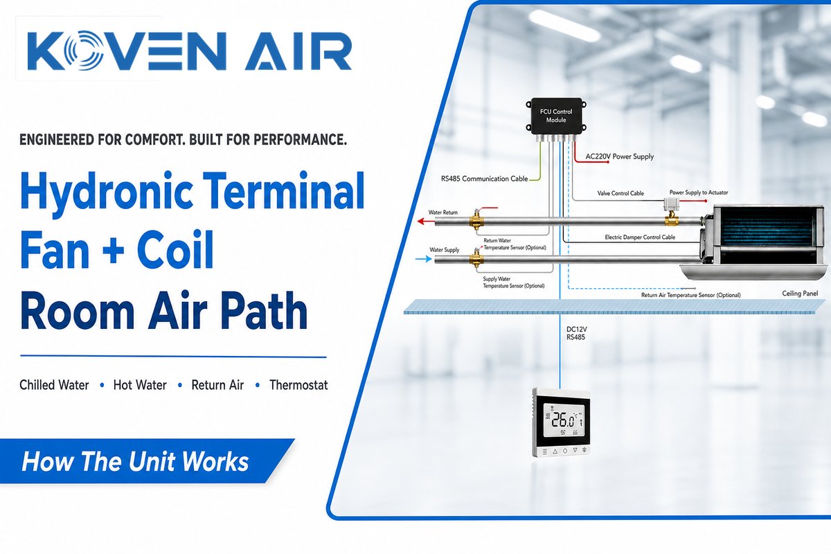
A concealed fan coil unit, often shortened to concealed FCU, is a local heating and cooling terminal. Its fan pulls room air through a filter and across a coil supplied by chilled water, hot water, or in some systems a refrigerant circuit. Conditioned air then returns to the room through an outlet grille or short duct run, while the cabinet stays above the ceiling or inside a service void.
A practical trade-off is that a horizontal concealed fan coil unit or ceiling concealed chilled water fan coil unit hides the cabinet but not the engineering risk. In practice, Koven Air buyers still need to verify measurable items such as a 15 min drain test, 50 Hz power supply, or 20% airflow margin because labels like ceiling concealed FCU, concealed fan coil, and ducted fan coil unit do not prove installed performance.
In a hydronic fan coil layout, the central plant does the heavy heating or cooling work through a chiller, boiler, air-to-water heat pump, or similar source. Zone comfort is handled locally. That makes the concealed FCU useful in hotels, offices, apartments, clinics, and light commercial spaces where each room or zone needs local comfort but the ceiling design can’t tolerate exposed equipment. For a public operating-data example, Lawrence Berkeley National Laboratory’s simulated fan-coil-unit data set treats fan-coil performance as measured system behavior, not as a model-name assumption.
Don’t confuse a concealed FCU with a dedicated outdoor air system, but don’t make the opposite mistake either. ASHRAE’s room air distribution chapter describes fan-coil units as factory-made assemblies that can perform some combination of temperature and humidity control, ventilation, filtration, and room air distribution. ASHRAE also distinguishes fan-coils from unit ventilators, which are designed for higher outdoor-air percentages. In a concealed FCU guide, that means ventilation and air quality are system-design questions, not catalog assumptions: outdoor air still has to be calculated, supplied, balanced, and controlled by the building design.
In practice, a local fan coil can be designed to work with outdoor-air equipment. ASHRAE terminology describes a dedicated outdoor air system as separate equipment that conditions outdoor air and delivers it to occupied spaces, either directly or with local HVAC units serving those spaces. Ask which configuration is being used: direct-to-zone outdoor air, outdoor air to the local-unit intake, supply-side mixing through a collar or mixing box, or ceiling-plenum delivery. Each path changes balancing, occupied fan runtime, backflow risk, filtration, condensation risk, and zone air distribution.
| Outdoor-air path type | Design check | Failure mode to avoid |
|---|---|---|
| Direct to room | Precondition, dehumidify, filter, and deliver near room temperature. | Draft, humidity complaint, or unbalanced ventilation when the FCU fan is off. |
| To FCU intake plenum | Balance outdoor air against return air and confirm occupied fan runtime. | Outdoor air shortfall, backflow, or poor distribution at low fan speed. |
| Outdoor-air collar or mixing box | Confirm measuring/control devices and damper behavior. | Wind or pressure variation changes outdoor-air volume beyond design intent. |
| Ceiling-plenum delivery | Check plenum pressure, insulation, filtration, and condensation risk. | Cold-air effects, ceiling condensation, or uneven zone ventilation. |
When outdoor air is delivered to a local-unit intake, the local fan may need to run throughout occupied hours. If that fan cycles off or modulates too far down, the actual outdoor-air volume and air distribution can fall below the ventilation design intent. Warm or poorly mixed supply air can also require a zone air distribution effectiveness review under the ventilation design, especially when the FCU is doing more than simple room recirculation.
That makes outdoor-air integration a design path to specify, not merely a risk to avoid. ASHRAE DOAS guidance describes conditioned outdoor air supplied to the intake of local units, including fan-coils, as one way required outdoor airflow can be delivered when the fan operation, pressure relationships, balancing method, and backflow controls are handled correctly. Put the outdoor-air source, measuring point, damper behavior, occupied fan runtime, balancing report, and low-speed verification method into the submittal instead of leaving them as field assumptions. If the outdoor-air volume can’t be measured and held during occupied low-load operation, treat the collar or intake connection as unresolved.
When Concealed Units Fit Better Than Cassette, Wall, Floor, or Exposed FCUs
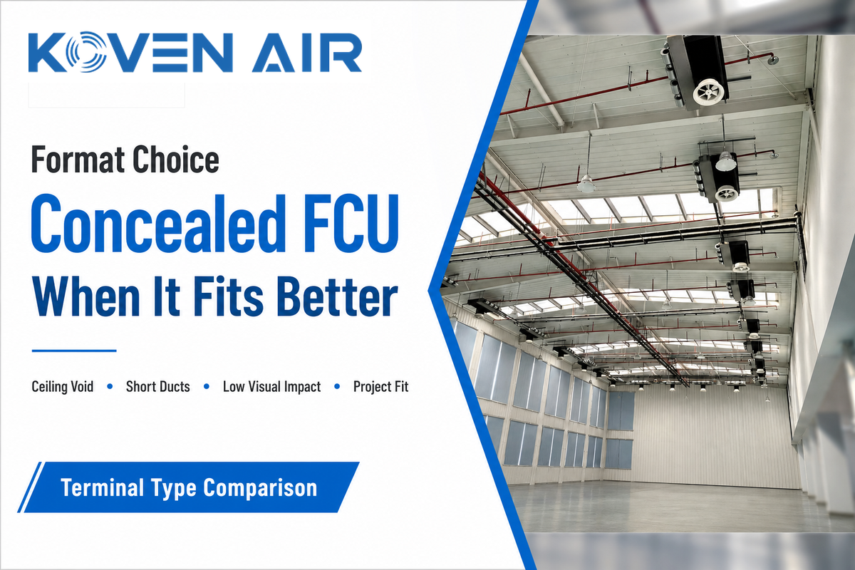
Concealed format is most effective when there’s a need for a clean ceiling or wall surface and the structure is able to provide access above the finished plane. It isn’t inherently superior to a cassette fan coil unit, vertical fan coil unit, under window unit or exposed cabinet. Selection is based upon plafond height, duct reach, service labor, return-air route, and occupant acceptance of the equipment.
In practice, the risk is not that cassette or wall units are better; it is that the concealed application hides a 15 min drain test, 700 rpm fan choice, or 35 dB(A) room target behind finished construction. Koven Air buyers should compare formats because the trade-off changes with service staffing, ceiling height, and return-air route.
| Room category / condition | Concealed FCU fit | Why it matters |
|---|---|---|
| Hotel guest room with corridor access | Strong | The unit can serve a quiet room while service access stays predictable. |
| Open office with exposed ceiling design | Mixed | An exposed or cassette format may need less hidden duct coordination. |
| Retrofit with shallow ceiling void | Risky | Cabinet height, drain fall, and duct collar space can become the limit. |
| Retail unit with frequent layout change | Mixed | Grille locations and partitions may shift after installation. |
| Apartment corridor ceiling with access panels | Strong | Maintenance can be planned outside the occupied space. |
| Cleanliness-sensitive clinic or lab room | Engineer review | Filtration, cleanability, condensate access, and healthcare or lab ventilation rules may rule out a standard FCU. |
| Room needing quick filter access by staff | Check first | Hidden filters save appearance but can raise service time. |
| Space with strict acoustic target | Check first | Duct lining, fan speed, and grille placement decide the final result. |
| Existing central hydronic loop | Strong | The fan coil can use chilled or hot water already available. |
| Room needing fresh outdoor air from the unit | System-specific | Some FCU configurations can mix or receive outdoor air, but the ventilation path, controls, and balancing still need engineering confirmation. |
Regulated healthcare rooms need a harder stop than ordinary commercial rooms. ASHRAE healthcare context warns that fan-coil systems can be less desirable in many hospital applications because filtration, enclosure cleanliness, and room-air recirculation limits may dominate the equipment decision. Local classification also matters: NYC Buildings’ mechanical key project terms show why mechanical scope can become an authority-having-jurisdiction question instead of a product-style choice. Use this guide for comfort-system screening, not for infection-control, pressure relationships, no-recirculation spaces, HEPA filtration cases, space-specific air-change rules, or ASHRAE/ASHE 170 classification.
7-Check Ceiling Fit Test Before You Specify One
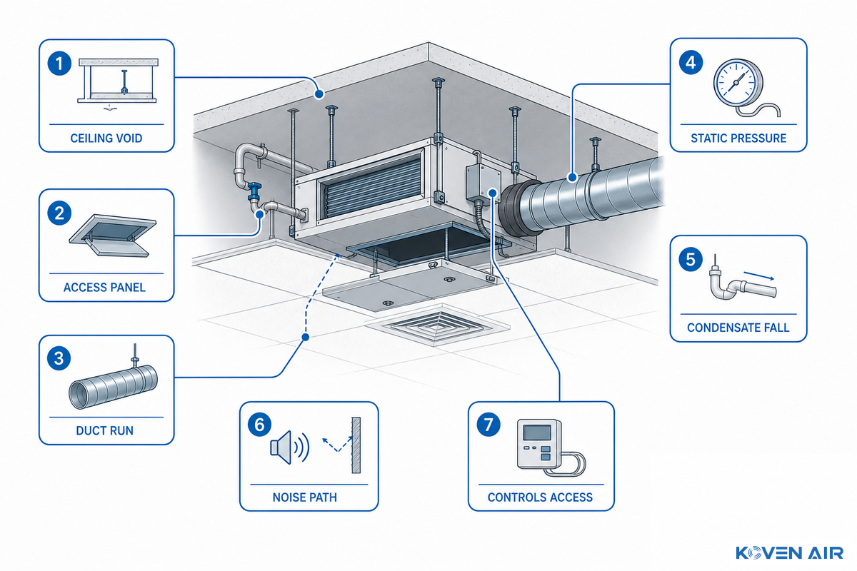
To reduce concealed FCU risk, run a fit test before model selection. Use this as a meeting checklist with the engineer, contractor, ceiling contractor, controls supplier, and facilities team. If any row is unknown, the unit may still work, but the project isn’t ready for final selection.
| Check | Target question | Failure mode if ignored |
|---|---|---|
| 1. Ceiling void | Is there enough height for cabinet, hanger, duct collar, insulation, and panel swing? | Unit fits on paper but not above the finished ceiling. |
| 2. Service panel | Can the filter, motor, valve, drain pan, and control box be reached without demolition? | Maintenance becomes a ceiling-cutting job. |
| 3. Supply duct run | Is the duct path short enough for the unit external static pressure? | Low airflow, high fan speed, or noise complaints. |
| 4. Return-air path | Is the return grille or plenum sized for free airflow? | Fan starves and the room never reaches setpoint. |
| 5. Condensate fall | Can the drain pipe slope to a safe drain, or is a pump required? | Overflow, ceiling stains, and shutdown alarms. |
| 6. Pipe insulation | Are chilled-water pipes and drain lines protected from ceiling-void dew point? | Hidden condensation drips onto ceiling materials. |
| 7. Noise path | Will fan, duct, grille, and ceiling structure transmit sound to the occupied zone? | Hidden unit becomes an audible unit. |
| 8. Controls access | Can the 24VAC thermostat, valve actuator, and control wiring be checked later? | Small control faults take too long to diagnose. |
| 9. Fire and ceiling coordination | Do access panels, duct materials, dampers, and insulation match local requirements? | Late redesign after inspection or commissioning. |
Notice that only two of the nine checks are capacity related. Concealed fan coil units fail in the field when the hidden parts around the cabinet are treated as secondary. Cabinet, air path, water, condensate, wiring, and technicians all need a working route.
Treat service access as a code and replacement-path issue, not only a convenience item. IMC 306.1 access language for appliances and HVAC components requires access for inspection, service, repair, and replacement without removing permanent construction or unrelated systems, and the cited section includes a 30 inch by 30 inch working-space requirement at the control side. Model-code editions and local amendments vary, so verify the adopted code with the authority having jurisdiction; NYC Buildings’ mechanical terms are one example of why the access panel and local classification should be checked before the ceiling is closed. Coordination is still direct: draw the access panel, working space, and removal path before the ceiling is closed.
Record project values instead of relying on a label on the submittal. Useful examples include 150 mm access clearance, 25 mm pipe insulation, a 1 m service path, 30 cm panel swing, 250 mm access-panel width, 500 mm access-panel length, 6 months filter interval, 15 min drain test, 2 hours commissioning time, 10 sec alarm response, 24 V controls, 0.5 A actuator load, 50 W fan draw, 700 rpm fan speed, 50 Hz supply, 1.6 MPa coil pressure rating, 3 bar test pressure, 0.75 kW motor allowance, 2 kWh daily control estimate, 35 dB(A) room noise target, 45 min balancing allowance, 12 min alarm reset test, 20% airflow margin, 5 min water-flow check, 48 hours post-handover review, and 12 years replacement planning. These aren’t universal thresholds; they’re the kind of measured fields that keep the specification tied to the real ceiling.
Field review rule: if a technician cannot remove the filter, clean the coil, clear the drain, and reach the control box from the planned access panel, the concealed layout is still unresolved.
2-Pipe vs 4-Pipe: Match the Water Loop to the Building Load
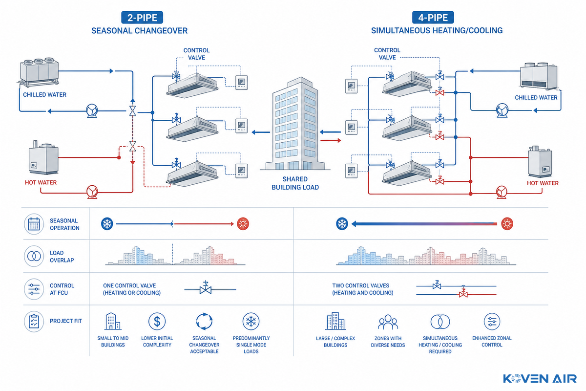
Concealed fan coil units come either as a 2-pipe or a 4-pipe unit. The 2-pipe fan coil uses one set of supply and return piping, where a single water circuit serves for either heating or cooling, based on the time of year and how it’s set up. In a 4-pipe fan coil, separate hot- and chilled-water loops provide for heating and cooling simultaneously when both are available via plant design and controls.
| Building load pattern | 2-pipe fit | 4-pipe fit | Selection note |
|---|---|---|---|
| Clear heating season and cooling season | Strong | Technically strong but higher first cost | 2-pipe can still work when changeover windows are predictable. |
| Perimeter rooms need heat while core rooms need cooling | Weak | Strong | 4-pipe handles load overlap better. |
| Hotel or apartment with many similar rooms | Project-specific | Project-specific | Compare comfort expectations, controls, and plant cost. |
| Budget-sensitive retrofit | Often stronger | Higher first-cost risk | 2-pipe may reduce piping, valves, and control points. |
| Mixed-use building with varied schedules | Risky | Often stronger | Simultaneous demand is more likely. |
| Climate with shoulder-season swings | Check carefully | Often stronger | Changeover timing can drive comfort complaints. |
| Simple owner operation model | Strong if changeover is accepted | Often easier in shoulder season | Four-pipe can simplify comfort operation, but it still adds physical components. |
| Room-by-room control expectation | Limited | Better | Controls and plant design still decide the final result. |
| Long-term maintenance staffing is thin | Often stronger | Check first | More parts can mean more maintenance unless access is excellent. |
If occupant comfort is the central criterion for system selection, then 4-pipe has a much stronger technical case. According to ASHRAE, 4-pipe distribution has a higher initial cost, but better comfort performance. That justification has four parts: simultaneous heating and cooling available in every unit all year round; no season changeover is required; controls are simpler; and a dead band between heating and cooling can be established. 2-pipe still has merit if cost, number of valves, and seasonal changeover predictability take precedence over simultaneously available comfort.
Be more cautious with 2-pipe systems in buildings that have variable load. ASHRAE points out that with a 2-pipe system, whether to heat or cool is dependent on supply water temperature, and that many systems that are less successful in variable conditions are where the supply temperature change throughout the day. If a building’s loads are split between heating and cooling in the same season, treat a 2-pipe system as a risk with clear owner acknowledgment, not just an inexpensive solution.
But the selection point has implications that go beyond a simple buyer’s guide. Consider the 2021 International Energy Conservation Code, commercial mechanical chapter, and verify the adopted edition through the local code path; the U.S. Department of Energy’s Building Energy Codes Program is a useful official starting point for model energy-code context. That 2021 IECC chapter includes thermostat deadband and setpoint-overlap controls, and it specifically forbids hydronic three-pipe systems because the hot and chilled water share a common return. It requires two-pipe systems to have explicit changeover controls, with at least a 15 F [8.3 C] outdoor-air temperature dead band between modes; operation for at least 4 hours in one mode before switching; and supply air temperatures no more than 30 F [16.7 C] apart at changeover. Although local codes may differ, it’s wise to apply those provisions, but not to approve a concealed FCU water-loop option until the controls can meet those requirements.
If your team is tackling an older building, it’s likely to encounter legacy three-pipe distribution. The ASHRAE guide identifies this distribution system as non-recommended due to its inefficiency and inability to meet most current energy codes. If replacing a concealed FCU in such a system, this should be handled as an engineer calculation and energy code review item, rather than a standard catalog selection.
Sizing, Coil Velocity, and Motor Checks Product Pages Usually Skip
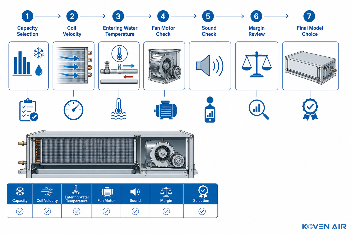
Even a unit that fit the ceiling can disappoint if the sizing basis is wrong. Oversizing a fan coil isn’t a reliability upgrade; it can shorten runtime, increase stratification, and make humidity control harder. ASHRAE terminal-equipment selection guidance notes maximum FCU airflow selection in the 70% to 85% rated-capacity range, chilled-water coil air velocity at or below 2.5 m/s, and coil-tube water velocity at or below 2.4 m/s to reduce condensate carryover, copper erosion, and pinhole leakage risk. LBNL fan-coil-unit data is another reminder that fan-coil behavior is evaluated through operating conditions and measured variables, not through catalog capacity alone. Treat those values as engineering checks against the manufacturer’s certified data, not as catalog copy.
Separate certified ratings from project-duty calculations. AHRI’s Room Fan-Coils certification page points to AHRI 440 and lists certified ratings such as total cooling capacity, sensible cooling capacity, and power input at specified speeds and temperature conditions; it also describes room fan-coils as generally having maximum design external static pressure at or below 1.0 in. H2O [0.25 kPa]. Use certified ratings for comparability, then verify the actual concealed duct run, water pressure drop, sound target, and control sequence as project-specific duty-point checks. If the installed duct and return path push beyond the certified room fan-coil boundary, the AHRI rating isn’t proof that the selected unit will deliver the same capacity, sound, or power result in the ceiling.
| Selection point | Check before approval | Why it changes the order |
|---|---|---|
| Airflow selection | Is maximum airflow inside the recommended 70% to 85% rated-capacity band? | Oversizing can reduce runtime and leave humidity or stratification problems. |
| Coil air velocity | Is chilled-water coil air velocity kept at or below 2.5 m/s? | High face velocity can blow condensate off the coil into the cabinet or toward electrical components. |
| Coil water velocity | Is water velocity kept at or below 2.4 m/s in coil tubing? | Excess velocity can erode copper and create leakage risk. |
| External static pressure | Do ductwork, diffuser, grille, filter, and return path losses match the fan curve and certified rating boundary? | Units selected near the fan-curve edge, or beyond a low-ESP room fan-coil scope, have little room for future changes. |
| Sound data | Does the selected airflow meet the room sound criteria at the intended fan speed? | Hidden units can still transmit fan, duct, and outlet noise into the room. |
| Motor type | Is the unit using PSC or ECM, and does the control sequence match that motor? | Motor choice changes fan modulation, valve control, energy use, and thermostat scope. |
Duct, Return Air, and Static Pressure Checks That Prevent Weak Airflow
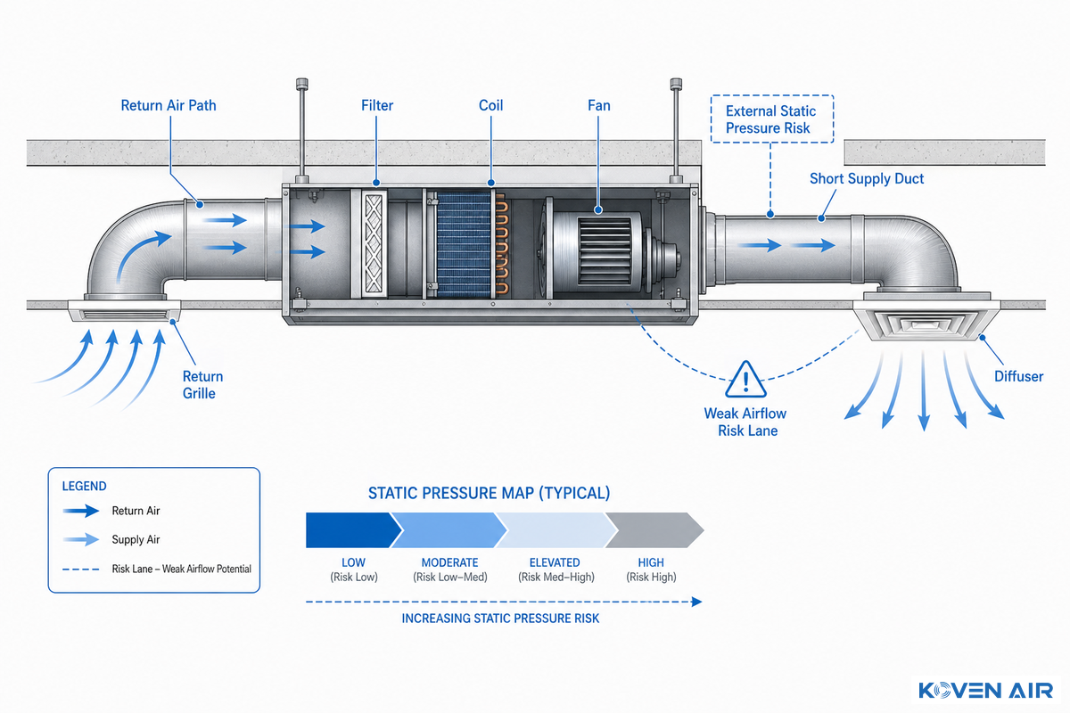
No matter how carefully a concealed ducted FCU is selected, it will underperform if its air path is compromised. Even short duct runs can build enough resistance to keep the unit from delivering rated airflow. Undersized grilles, sharp elbows close to the unit, blocked ceiling plenums, and diffusers chosen for appearance instead of throw can all leave the room cold, warm, noisy, or uneven.
Before the concealed fan coil unit is ordered, confirm three numbers: the design airflow in CFM or m3/h, the available external static pressure from the selected model, and the pressure loss of the supply and return path. Catalogs can list 200 to 1,200 CFM or more depending on model family, but the final room result depends on the installed ductwork, grille, filter, and return path. Public fan-coil performance data such as LBNL’s simulated fan-coil-unit data set reinforces the same point: airflow behavior has to be checked as an installed condition.
For Koven Air buyers, the practical problem is that a 200 CFM room unit and a 1,200 CFM room unit can both fail in the field if the duct path is forced beyond the fan curve. That is why a 20% airflow margin, 45 min balancing allowance, and measured return-air path should be part of the application review, not an after-sale correction.
When dealing with longer or complex duct runs, resist the urge to have a standard concealed fan coil emulate a high-static air handler. Select a unit and fan speed that will adequately deliver external static pressure to the system without generating excessive noise. If your design requires the fan to run at its maximum speed to achieve desired airflow, there’s not much room for error for clogged filters or future diffuser adjustments.
Target acoustic criteria beyond the published sound data. Integrate design room noise levels (NC, RC, dB(A)), grille specifications, interior duct liner, vibrational isolators, fan speed, and ceiling transmission into the selection and review process before you place a concealed FCU above an office, conference room, guest room, or clinic.
If the fan coil utilizes a ceiling void, interstitial space or soffit as a return air plenum, verify that design. ASHRAE’s guidance on fan coils states that a Fur Down, horizontal-mount unit can use a soffit or interstitial space as a return plenum; you must then also consider return grille location, plenum pressure drop, air leakage, cleanliness and access.
Geometry of the occupied space can be just as influential as ductwork. ASHRAE also points out that improperly located return grilles may reduce coil effectiveness and cause uneven heating and cooling. Short-circuited supply air, air drafts from the return, proximity to the exterior envelope or heat-producing sources are among potential problems that impact thermostat operation.
For office buildings, the best selection is often the horizontal concealed FCU that keeps the heat exchanger, drip tray, air outlet, filter, and control valve actuators reachable through a ceiling opening. HVAC designers may also require factory-assembled valve packages, supply air and entering water temperatures, and fan-speed data so high efficiency claims do not raise energy use or compromise quiet operation.
Condensate, Insulation, and Service Access Mistakes to Catch Early
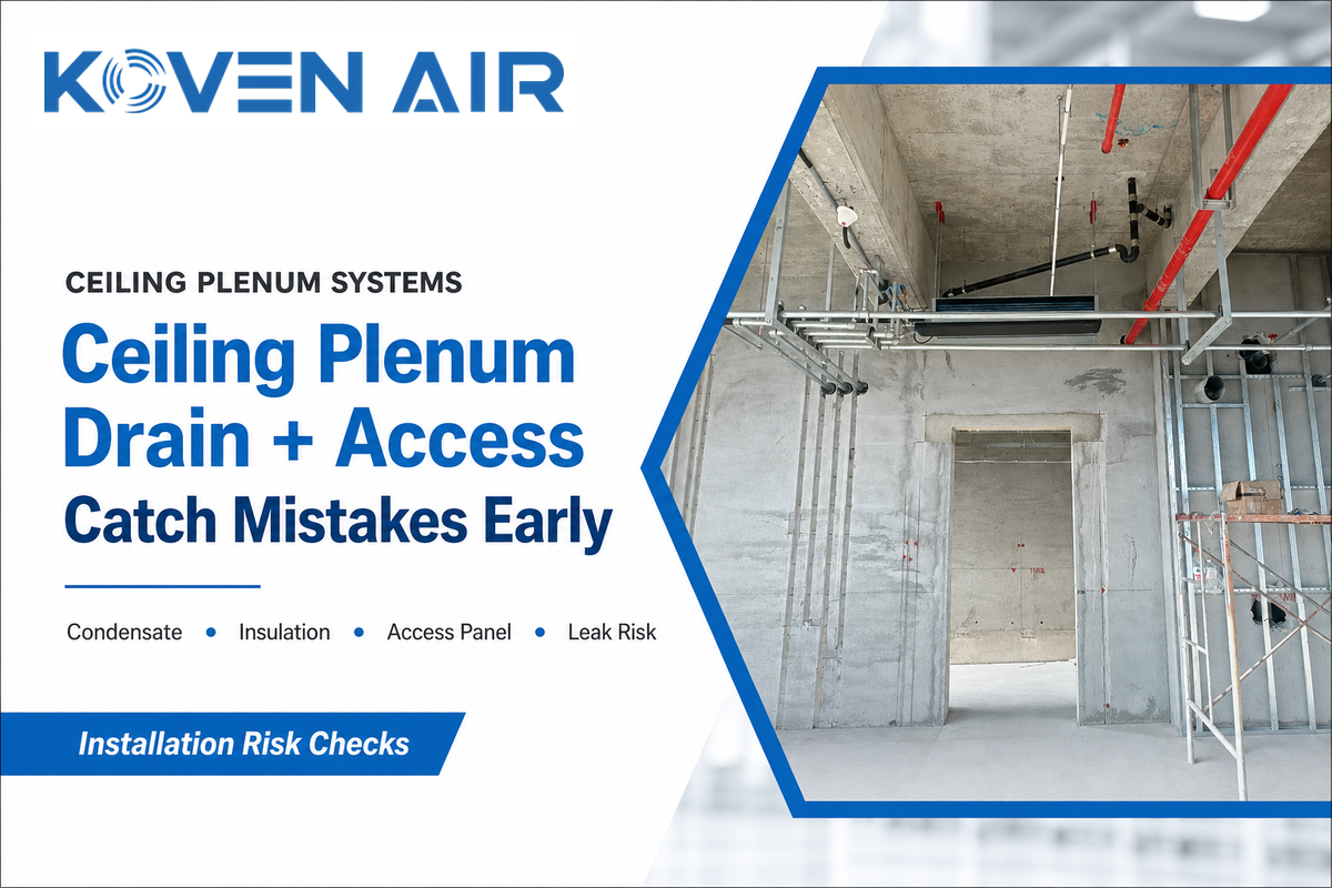
When cooling coils produce moisture, surface temperature needs to be below room air’s dew point to dehumidify the air; that water needs an escape path. Sloping of drain lines, trap design, drain-pan access, pipe insulation, and pump reliability decide whether a concealed FCU is manageable in the field. Technician discussions often point to the same problems: clogged drains, poor slope, missing traps, and hard-to-reach pans becoming recurring service calls.
Condensate is also a code coordination item, not just a maintenance preference. Under the 2024 International Mechanical Code section on auxiliary and secondary drain systems, auxiliary pans, separate drains, or water-level detection are required in defined cases where overflow from coils can damage building components. Verify the adopted model-code edition and local amendments before writing final details. For this guide, the risk is overflow, leakage, access, and maintenance; it should not be stretched into a broad microbial claim. OSHA notes that properly drained condensate pans below cooling coils are normally not a Legionella source because the water temperature is low.
Arrangement is also important. ASHRAE stated horizontal draw-through fan coils can have a more uniform airflow and quieter noise levels but condensate blow-off can fall onto electrical components with an improper selection or arrangement. This can integrate the duct, sound, coil velocity, drain pan, and control-box location into one approval question.
| Risk area | Early warning sign | Design response |
|---|---|---|
| Primary drain | Drain has no steady fall to an approved point | Revise route or add a pump with service access. |
| Trap and vent | Negative pressure can hold water in the pan | Follow manufacturer and local drainage requirements. |
| Secondary pan | Ceiling below has high damage risk | Plan overflow detection or a secondary pan where required. |
| Pipe insulation | Chilled lines pass through humid ceiling voids | Insulate chilled-water and drain sections at risk of sweating. |
| Filter service | Filter cannot slide out cleanly | Move access panel or choose another orientation. |
| Coil cleaning | Motor/blower assembly blocks the coil face | Check removal clearance before closing the ceiling. |
| Valve service | Control valve is hidden behind ductwork | Relocate valve package or add service space. |
| Control box | Technician must remove ceiling grid to test wiring | Keep junction box reachable from the access opening. |
| Commissioning | No test point for airflow, water flow, or drain operation | Include balancing and drain checks before handover. |
Controls and Thermostat Choices for Concealed FCUs
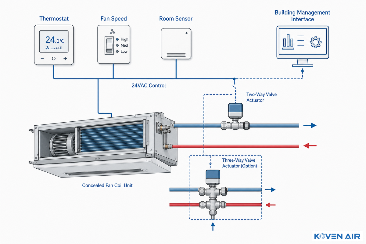
Control selections should be made with the equipment choice, not once the ceiling is closed up. Basic concealed FCUs may have on/off control, 24VAC thermostat, three-speed fan selection, and a two-way or three-way valve. More advanced applications may connect to a building management system and include room temperature sensing, fan speed control, valve actuator feedback, and alarm annunciation. Practically, if the owner cannot see drain alarms or valve faults, a hidden unit can turn a small control issue into a room complaint.
In practice, the control risk exists because a 10 sec alarm response, 24 V controller, 0.5 A actuator load, or 50 Hz supply fault is often invisible to occupants until comfort fails. Koven Air buyers should confirm the sequence of operation before the ceiling closes, especially when the local fan must run for outdoor-air delivery.
Ask three questions to clarify the controls scope. Will the thermostat be local, networked, or both? Will the fan run on low, medium, high or cycle on load? Who needs to be notified of drain overflows, valve failures or communications losses? Those answers affect the electrical, access, cost, and owner’s handover process.
For 4-pipe concealed FCUs, ask an additional question: how will the control sequence prevent the heating and cooling modes from battling one another? Dead band, valve sequence, fan mode, and occupancy schedule need to be written before commissioning. If the layout involves ventilation-assisted applications, also verify whether the local fan needs to run during occupied hours to deliver the intended outdoor air.
Energy compliance is an engineer calculation issue. Terminal fan energy, operation of the hydronic pump, dead band control, setpoint overlap, occupancy schedules, the timing of two-pipe changeover, and the avoidance of simultaneous heating and cooling will be checked against the adopted energy code and project control sequence, not against a checklist found in a blog. Use an official code-adoption path such as the U.S. Department of Energy’s Building Energy Codes Program as context, then confirm the enforceable local edition. Submittals should contain the sequence of operation, not just the brand name of the controls.
Motor choice should also be in this discussion. ASHRAE’s fan coil control section noted that both PSC and ECM motor selections can impact sequence of operations, thermostat type, controls and water valves. With ECM arrangements the fan motor and water control valve can modulate in accordance with room demand. For concealed ceiling units, this can have an impact on energy consumption and the level of control authority the owner receives.
Recent patent filings related to fan speed, noise thresholds and control communication suggest that the industry is still developing the control behaviour of systems and not only coil capacity. For the customer this means a control schedule is now a specified design item rather than a low-end add-on product.
Maintenance and Replacement Planning for Concealed Units

A concealed fan coil unit should be specified with the maintenance route in mind. Filters, coils, drip tray or drain pan, fan motors, and control valve actuators all need access. If the service panel is too small or blocked by a light fixture, the building may pay for that choice every maintenance cycle.
FacilitiesNet notes that fan coil systems can require added maintenance for filter replacement and condensate pan cleaning because those items live at the terminal unit. That is not a reason to reject concealed FCUs. It is a reason to make access a drawing-level item before purchase.
Plan maintenance frequency, not only access geometry. ASHRAE cautions that in-room terminal filters are often small and low efficiency, can need frequent changing, and that concealed ceiling or soffit units can make proper coil cleaning difficult. Condensate-pan maintenance also needs a narrow, evidence-based scope: OSHA’s Legionnaires’ disease control guidance notes the importance of proper drainage while distinguishing normally cool, properly drained condensate pans from broader microbial claims. Practical submittals should include filter size, spare-filter stock, coil cleaning route, and who owns the recurring labor.
Koven Air’s KAFP product page reports reviewed first-party figures: a 2,232-unit deployment, a 0.32% cumulative failure rate, and annual maintenance cost under CNY 60 per unit for that field record. Treat those as Koven Air field notes, not as universal industry averages. For this guide, practical value comes from showing that large concealed-unit projects need repeatable maintenance access, not only a correct load calculation.
2026 Demand Signal: Why Ceiling-Concealed Queries Need Fit-Check Content
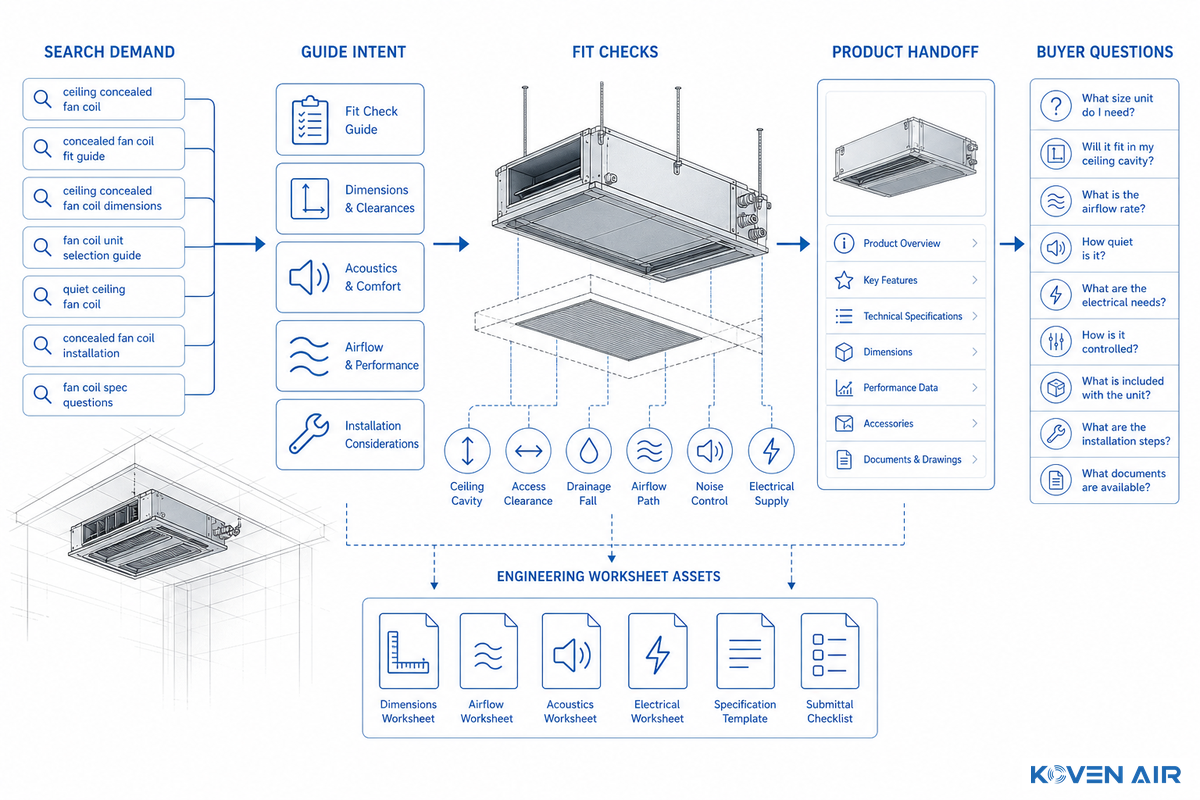
Search data also points toward a need for practical specification content. A Google Ads keyword dataset shows “ceiling concealed fan coil unit” moving from 50 monthly searches in March and April 2026 to 110 in May and 140 in June 2026. That isn’t a market-size claim. It’s a search-demand signal from the local keyword dataset: more users are looking for the ceiling-concealed version, and those users need fit checks before product comparison.
This is where a guide should differ from a product page. Product pages can show KAFP sizes, BTU/h range, duct-sizing data, and request-a-quote options. Guide content should help the reader decide whether the project is ready for that product comparison. If you have already confirmed ceiling void, duct path, drain route, 2-pipe or 4-pipe loop, and controls scope, you can move to Koven Air’s concealed FCU product details with fewer unknowns.
Discuss a concealed FCU project
FAQ
Use these answers as buyer-screening notes, not as final engineering decisions. Risk remains when a unit is selected by name only because access, condensate, static pressure, and controls still decide whether a concealed FCU works in the field; Koven Air model selection should follow only after those checks are known.
What is a concealed fan coil unit?
This heating and cooling terminal is hidden above a ceiling or inside a service void. It uses a fan to move room air across a coil supplied by chilled water, hot water, or another matched system source. Air then returns to the room through grilles, short ducts, or a plenum. It is chosen when the room needs local comfort control without a visible wall, floor, or exposed ceiling cabinet.
Does a concealed fan coil unit need ductwork?
Many concealed units use short supply ducts, outlet plenums, or return-air paths, but they do not always need long central duct runs. Check whether the selected unit has enough available external static pressure for the installed supply and return path. Duct length, elbows, grille selection, filter pressure drop, and return-air opening size all affect airflow. Hidden units with poor duct design can still create weak cooling, noise, or uneven room temperature.
What is the difference between a concealed fan coil and a ducted fan coil?
These terms often overlap, but they describe different parts of the design. “Concealed” describes where the unit is located, usually above a ceiling or inside a hidden void. “Ducted” describes how air is delivered from the unit to the room. Concealed fan coils may be ducted to supply grilles, may use a short plenum, or may use a return-air grille near the unit. Specification still needs separate checks for access, drain, static pressure, and controls.
Is a 2-pipe or 4-pipe concealed FCU better?
Neither layout is always better. For clear heating and cooling seasons, a 2-pipe concealed FCU is simpler. Projects where some zones may need heating while others need cooling simultaneously usually fit 4-pipe better. Base the choice on load overlap, plant design, controls, budget, and maintenance capability.
How much ceiling space does a concealed fan coil unit need?
Needed ceiling space depends on the cabinet height, hanger detail, duct collar, insulation, drain slope, valve package, and service panel. Do not check only the unit height in the catalog. Confirm the full installed depth and the clearance needed to remove filters, clean coils, service the fan motor, and reach the control box. For a real project, the ceiling plan should also show where the access panel opens, whether the drain can keep a steady fall, whether the duct collar conflicts with beams or lights, and whether the valve package can be isolated without removing finished materials. Even a shallow void can work, but only when these details are drawn and checked before the unit is ordered.
What maintenance access should be planned?
Plan access for filter replacement, coil cleaning, drain pan inspection, condensate line clearing, fan motor service, valve actuator checks, and thermostat or controller troubleshooting. Match the access panel to the service path, not merely the cabinet outline. If a technician cannot remove the filter or reach the drain pan without damaging the ceiling, the concealed layout has not been fully coordinated.
References
These sources are included because concealed FCU risk is often hidden in access, condensate, ventilation, and controls rather than in the model name alone. They support the 15 min drain-test example, the 30 inch working-space reference, the AHRI rating boundary, and the Koven Air commercial handoff.
- NYC Buildings: Mechanical key project terms
- Lawrence Berkeley National Laboratory: simulated fan coil unit data set
- ASHRAE Handbook: room air distribution equipment
- ASHRAE Standards 62.1 and 62.2
- ASHRAE Terminology: dedicated outdoor air system
- 2024 International Mechanical Code: auxiliary and secondary drain systems
- IMC 306.1: access and working space context
- ANSI: ASHRAE/ASHE 170-2025 healthcare ventilation context
- EnergyPlus Engineering Reference: zone forced air units
- 2021 IECC Chapter 4: commercial energy efficiency controls
- U.S. Department of Energy: Building Energy Codes Program
- ASHRAE Handbook: four-pipe distribution context
- ASHRAE Handbook 2016: HVAC system analysis and selection context
- ASHRAE Handbook 2016: fan-coil unit outdoor-air, two-pipe, and motor-control context
- ASHRAE Handbook: dedicated outdoor air systems context
- OSHA: Legionnaires’ disease control and prevention
- AHRI: Room Fan-Coils certification program
- Google Ads keyword data source context
- FacilitiesNet: four-pipe fan coil unit systems
- Google Patents: fan coil control and noise-threshold context


![Commercial Rooftop Unit Guide: Types, Sizing & Costs [2026]](https://kovenair.com/wp-content/uploads/2026/07/commercial-rooftop-unit-guide-featured-2-150x150.png)