
Get in Touch with Koven Air Company

Cleanroom Dry Cooling Coil
ISO 5–8 Sensible Cooling for Semiconductor & Precision Environments
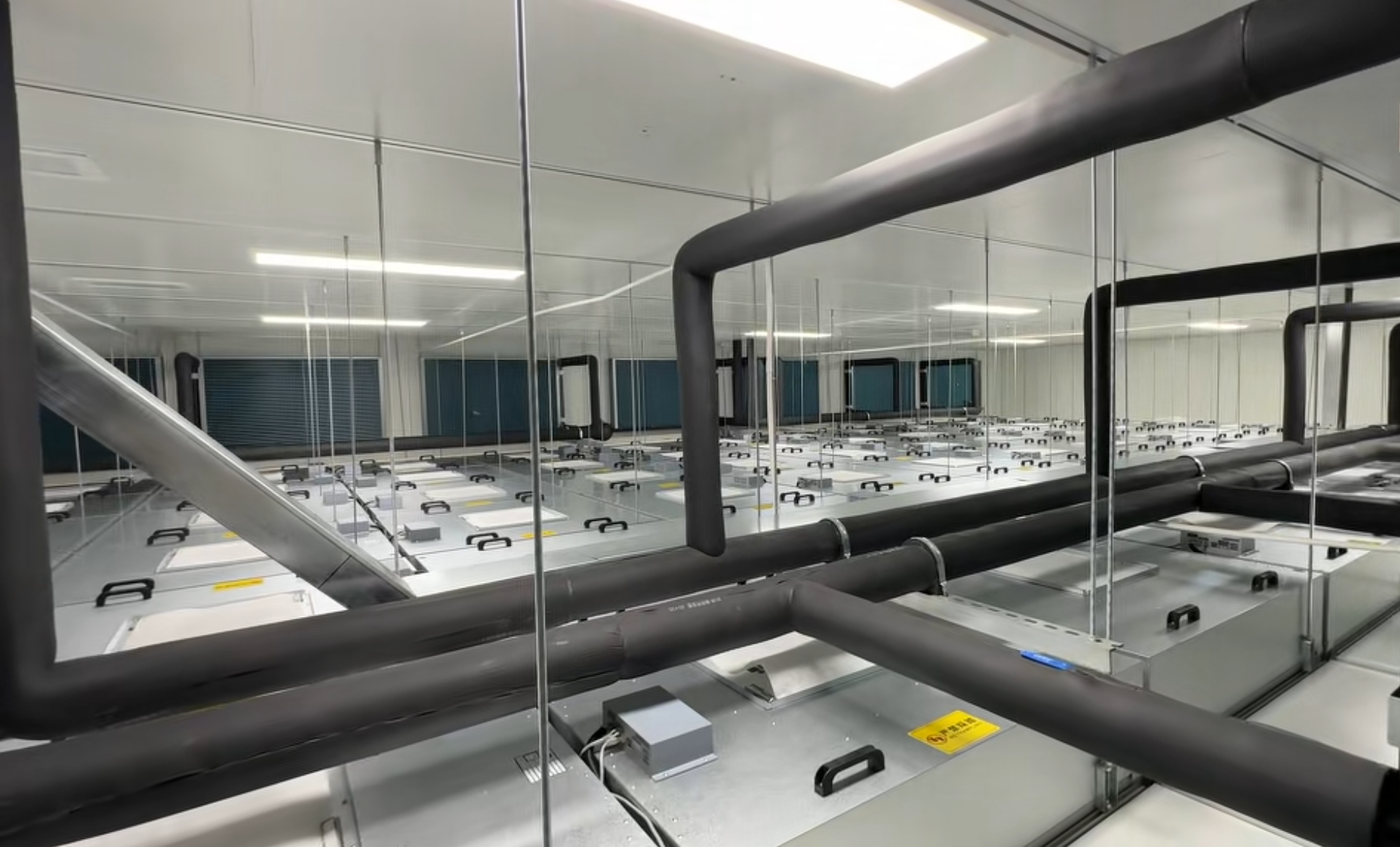
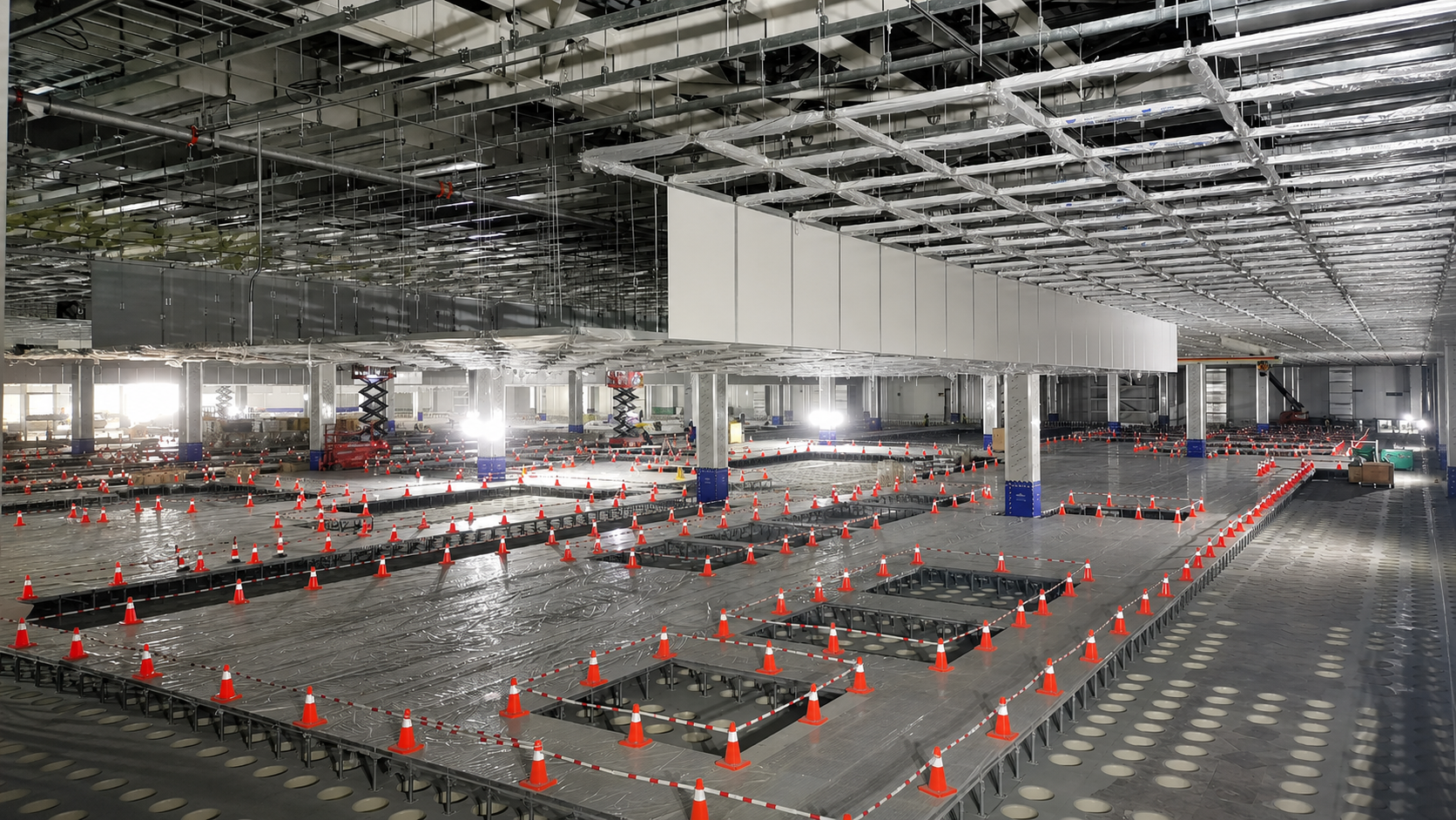
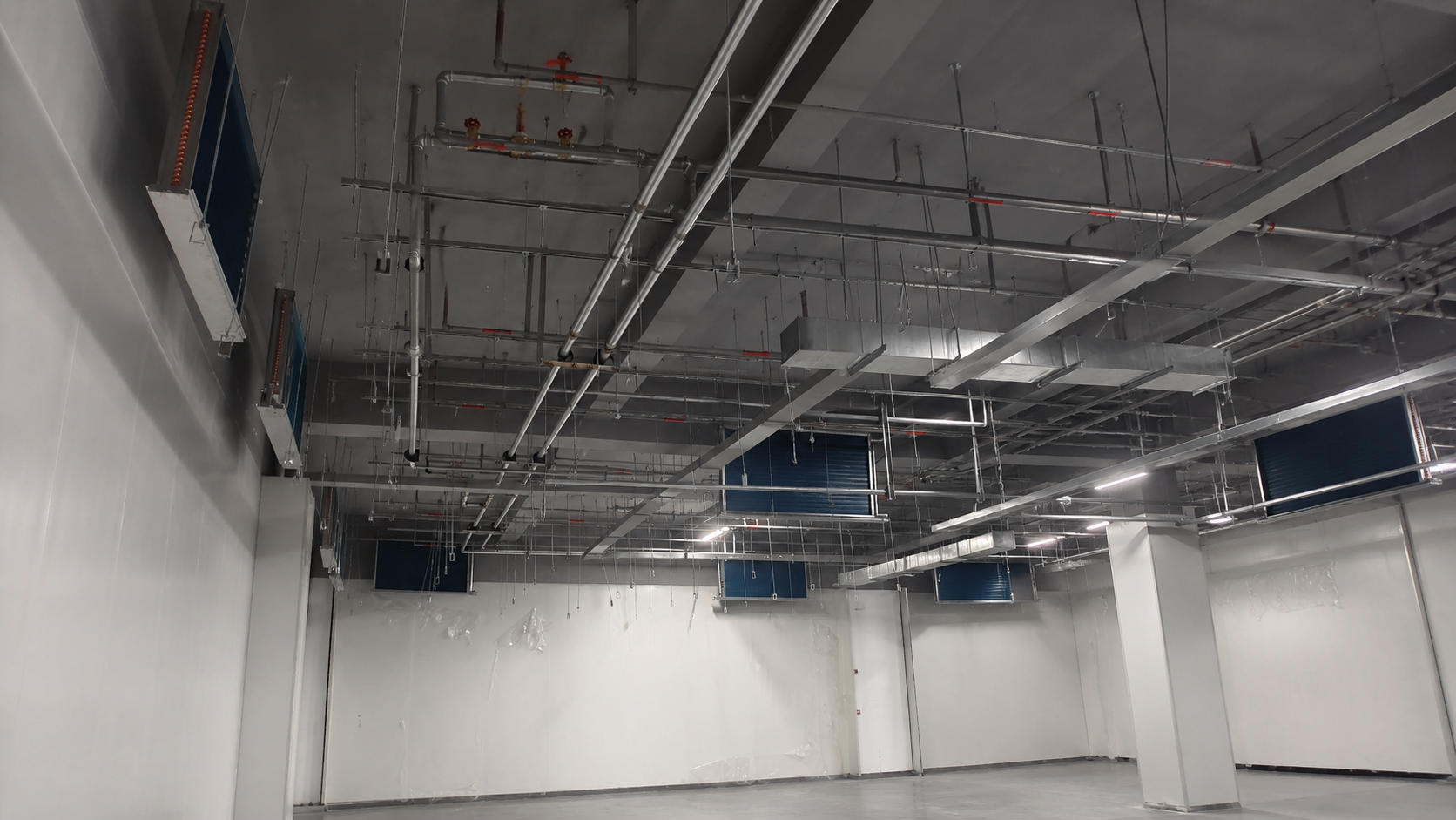
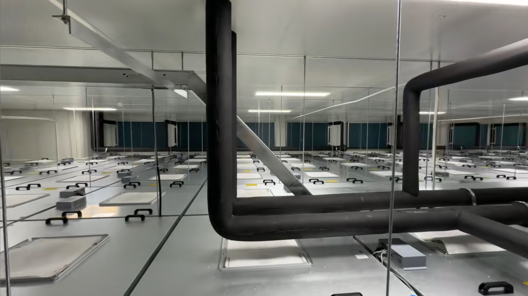
When used in the recirculated airstream of an ISO 5-8 cleanroom, Koven Air’s dry cooling coil system removes only the sensible heat load without generating any condensate—which is necessary to keep temperature control entirely independent of whatever dehumidification work the MAU is already handling. These are custom-designed, not off-the-shelf, copper or 304/316L stainless steel coils sized for your required face velocity, water-side pressure, and cleanliness class.
[ INTERACTIVE: CLICK TO SWITCH VIEWS ]
-
ISO 5–8Cleanliness class compatibility
-
0 condensateSensible-only operation
-
Cu / 316LCoil material options
-
13–14°C / 18–20°CTypical CHW supply/return
-
42.8–54.1%Lower annual energy vs. wet-coil*
-
MAU+FFU+DCCDecoupled system architecture
When Standard AHU Coils Compromise Cleanroom Humidity Stability
In a cleanroom’s MAU+FFU+DCC air conditioning system, a dry cooling coil (DCC) functions as the “sensible heat only” unit, withdrawing heat from recirculation air with mid-temperature chilled water held at a temperature that never drop to or below the room’s dew point. It’s that critical feature-the prevention of any coil condensation-that makes it so different from a conventional wet-coil cleanroom air handling unit (AHU) — unlike a standard AHU coil, it never has to fight condensation in the first place.
CONTAMINATION FLAW
Typical cooling coils are designed deliberately to deliver chilled water at or below the dew point-in order to strip moisture from the airstream. The unintended consequences of that strategy are a surface sitting in the airstream covered with stagnant, wet water that provides an ideal medium for microbial growth, exactly what cleanroom and GMP programs are aimed at preventing[1]. On top of that, condensation couples the temperature and humidity control setpoints in ways that make adjusting either a trade-off, an issue when semiconductor processes require separate setpoints to be fine-tuned.
Removing the source of the contamination instead of adding filtration at the outlet is the true contamination control solution.
13-14°C
SUPPLY WATER
~2°C
ABOVE DEW POINT
A cleanroom DCC operates on 13-14°C supply water (around 2°C above the return airstream dew point), so the coil surface never goes below dew point. Humidity control duty falls entirely on the MAU (make-up air unit), while the DCC handles only sensible load. The most common error encountered by mechanical engineers is using comfort-HVAC rules of thumb to calculate the cleanroom sensible cooling load, and only discovering midway that the load calculated by the process, the number of FFU/HEPA filters, and air changes require a detailed calculation rather than a broad estimation[2].
DESIGN SPEC NOTE: It’s worth mentioning one potential source of confusion upfront: even though the goal is the elimination of condensation during routine operation, the design specifications do recommend a condensate pan in cases where humidity may fluctuate to unexpectedly high levels or where there’s an issue with pipe insulation-the DCC removes the most frequent causes of condensation under operating conditions, but not necessarily any design lapses in pipe insulation or water temperature regulation.
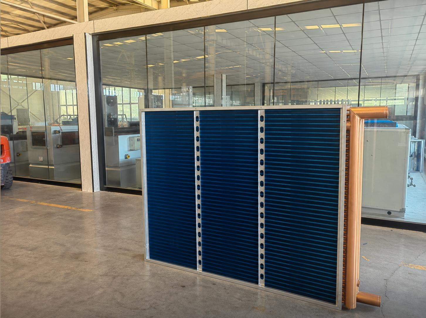
MANUFACTURING STANDARD
We build Koven Air cleanroom DCC units to those same design standards, and not some off-the-shelf commercial unit modified and sold on for a cleanroom. Each DCC unit we build is subject to a proprietary design process in-house prior to manufacturing and is put through a rigorous 24-hour aging test at our lab before shipment. That’s precisely the engineered approach that results in a superior performing custom DCC compared to an AHU coil simply specified to fit-our built-in design margins are present from the initial calculation onward.
Request Custom Design Review If your project is at the load-calculation stageCleanroom Cooling Integration — How DCC Works with FFU + AHU
CORE LOGICDCC never works in isolation. It’s inside a stack of three units, each doing exactly one job, which is why this architectural arrangement out performs any single, do-it-all AHU coil.
The EN section applies to RFQ matching as does PROC, which is part of it. DCC never works in isolation. It’s inside a stack of three units, each doing exactly one job, which is why this architectural arrangement out performs any single, do-it-all AHU coil.
An AHU that attempts all three jobs on a single coil is what most facilities default to outside the clean room – a single coil coil approach in the clean room is exactly what a decoupled MAU / FFU / DCC stack is intended to replace.
System Architecture Comparison
| Function | Single-Coil AHU | MAU+FFU+DCC |
|---|---|---|
| Humidity control | Combined with cooling | MAU handles independently |
| Temperature | Coupled to setpoint | DCC controls sensible only |
| Condensation | Present by design | None under correct margins |
| Cleanliness | Dependent on filter bank | Dedicated FFU with HEPA/ULPA |
| Zonal response | Whole-system cycling | Zoned independently |
Airside & Waterside Design Ranges
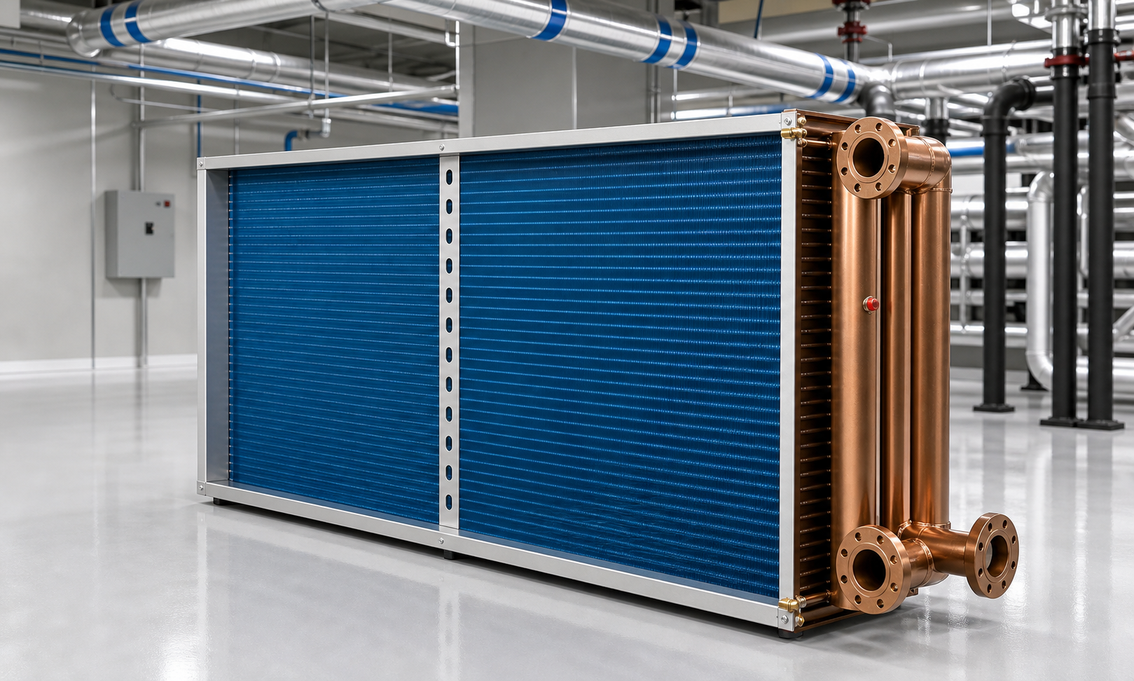
Hover to Expand Chart
0.6 – 2.5m/s
Target Face Velocity
We typically target a face velocity of the coil in the range of 0.6 to 2.5 m/s – the low end of the range means the heat transfer is less efficient and air distribution turns uneven, the upper end of the range can cause pressure drop of around 30 Pa or more and risks water entrainment off the fins when the room humidity is high. (Note: The exact range may vary by manufacturer but this convergence of manufacturer design guidance helps to confirm appropriate parameters.)
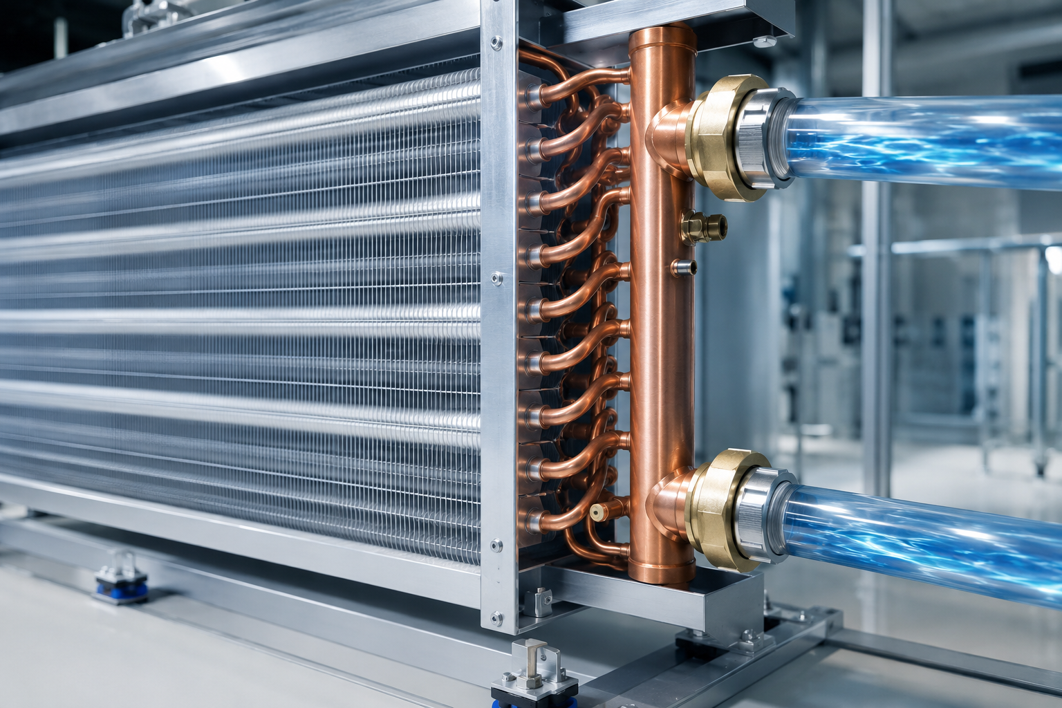
Hover to Expand Chart
0.8 – 1.8m/s
Water Side Velocity
We recommend targeting a water side velocity of 0.8-1.8 m/s – at lower values the coil heat transfer is impaired and at higher values the water side pressure drop may be too high (>50 kPa), increasing pump head and risk of water hammer during startup when a system may not be vented. (Note: There are a number of other considerations for coil selection, these represent the starting points and not the end result). These aren’t arbitrary selection criteria – they represent the fundamental design boundaries within which the selection process for a DCC coil starts, and they must be appropriately considered to avoid designing the unit “just like a standard AHU,” which many mechanical engineers cite as a complaint.
System Calculation Note: Koven Air engineers conduct this calculation based on your number of FFUs and room heat load prior to quoting. Unlike a general purpose coil manufacturer, our face velocity and water velocity numbers are specifically for your application, not a generic table.
ISO Class 5–8 Design Criteria — Matching Coil Selection to Cleanliness Level
EN and PROC. Clean room coil selection isn’t a one-size-fits-all approach. The more sensitive the cleanliness class of the clean room, the less pressure the fans have remaining in their available static pressure to overcome resistance after the clean room terminal filters. This dictates that as cleanliness increases, the face velocity, resistance and manufacturing requirements of the coil will change. Air Changes per Hour (ACH) applied to your supply air volume is usually the single specification that guides this selection. The table below is our ISO Class 5-8 to ACH/Filtration Design Mapping Table, built specifically to show that pairing at a glance.
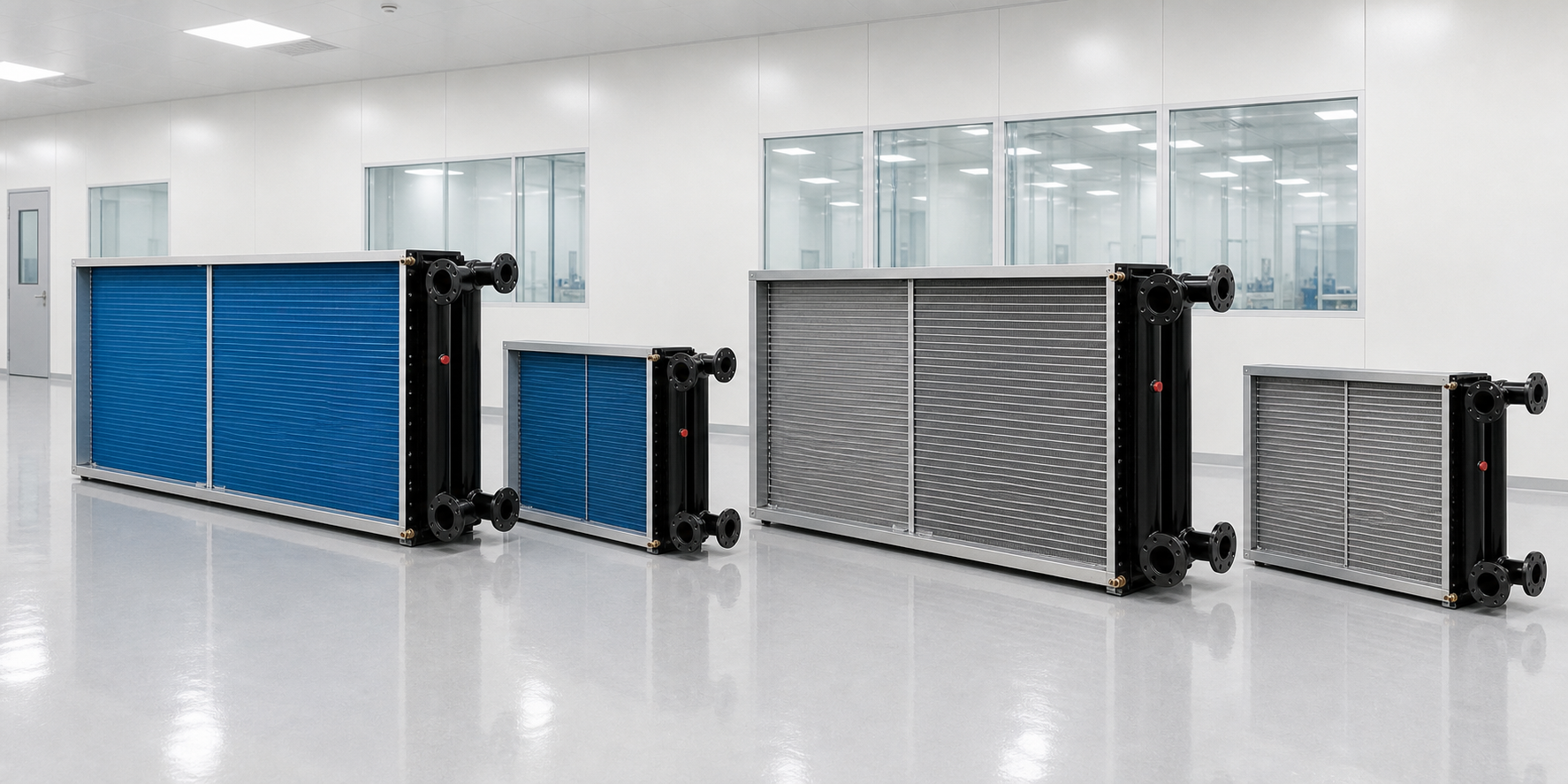
COIL SELECTION MAP
| ISO Class | ≥0.5µm limit (particles/m³) | Legacy FS209E | Airflow type | Typical ACH* | Terminal filter |
|---|---|---|---|---|---|
| ISO 5 | 3,520 | Class 100 | Unidirectional (velocity-based) | 240–480/h | U15/U16 ULPA |
| ISO 6 | 35,200 | Class 1,000 | Unidirectional/mixed | 90–180/h | H14/U15 |
| ISO 7 | 352,000 | Class 10,000 | Non-unidirectional | 30–60/h | H13/H14 |
| ISO 8 | 3,520,000 | Class 100,000 | Non-unidirectional | 5–60/h | H13 |
ACH is for industry experience design ranges, not a ISO 14644 requirement. Final ACH should be verified by room-specific HVAC load calculation. Particles according to ISO 14644-1:2015[1]. Filtration Classes per EN 1822. (H13 99.95%, H14 99.995%, U15 99.9995%, U16 99.99995%, all for MPPS)[3]. WHO/FDA pharmaceutical grade air-change rate range also supports the same design logic. (6-20ACH for grade D, 20+ for aseptic B/C)[4].
[ AIRFLOW DYNAMICS ]
ISO 5 and higher cleaner spaces generally use unidirectional airflow to push particles out. This is also referred to as laminar airflow. “Unidirectional” here describes the direction of air. It is thought of as moving in a straight column, like a piston of air going down, clearing particles from the room. Lower cleanliness classifications, like ISO 6-8, do not rely on unidirectional flow, but instead use non-unidirectional airflow that mixes room air.
The consequence of this difference in design approach is: an ISO 5 room with 240-480ACH will use far more recirculated air through its coil than a 5-60ACH ISO 8 room packaging area. The ISO 5 coil has to deliver the cooling to meet a sensible cooling requirement with the smallest available pressure drop because the ULPA terminal filters are already taking a large share of fan static pressure. Therefore, we configure our ISO 5-7 coil with a lower resistance fin spacing and larger face area than you would find on a standard commercial coil.
LOW ΔP
FIN: CUSTOM
ISO 5 LAMINAR
TRACEABLE
[ ENGINEERING ADVISORY & CUSTOMIZATION ]
Selection tip
For non-unidirectional airflow (ISO 7/8 cleanrooms), raw coil resistance becomes less critical than energy and cost. Simply specify your cleanroom coil based on your specific ACH, and not on the highest value for your class, as is a common approach that leads to over-design.
Our differentiator is that we don’t design off of standard, pre-selected commercial coil product lines, whereas a catalog-driven supplier typically does. A catalog coil offering provides only 2-3 face areas per series. We can manufacture a coil with any fin spacing you desire using precision machinery at our facility – and we’re able to do so with every batch traceable. If you know your desired ACH and heat load, send them to our engineering team for a sized quotation rather than starting from a generic spec sheet.
The Humidity Stability Advantage of Sensible-Only Cooling.
Slipping as little as 1-2% relative humidity off your setpoint, or letting uncontrolled humidity swings build static electricity, can trigger a semiconductor contamination alarm or result in a pharmaceutical batch failure. And this risk isn’t theoretical, but the direct outcome of attempting to manage temperature and humidity with a single, coupled system. Not only is this decoupled control necessary for cleanroom stability, but it also results in significant energy savings. A cold-heat offset study conducted on cleanroom control systems in semiconductor fabs indicated a 42.8% to 54.1% reduction in annual energy use by a decoupled DCC system compared to conventional (non-decoupled) systems. On top of that, the fully decoupled MAU + DCC + FFU system architecture proved to be the most energy- and cost-efficient[5]. Studies published in Energies note that cleanroom air conditioning accounts for 40-50% of total semiconductor fab energy use, which is why the fully decoupled system pays for itself in the facility’s operating expenses and not merely in equipment costs[6].
42.8–54.1%
Lower estimated annual energy use for MAU+FFU+DCC decoupled cooling vs. a conventional (non-decoupled) cleanroom cooling system
Source: peer-reviewed cold-heat-offset study of semiconductor cleanroom environmental control systems — figure describes decoupled-architecture performance generally, not a Koven Air lab measurement
01. NO-CONDENSATION DESIGN
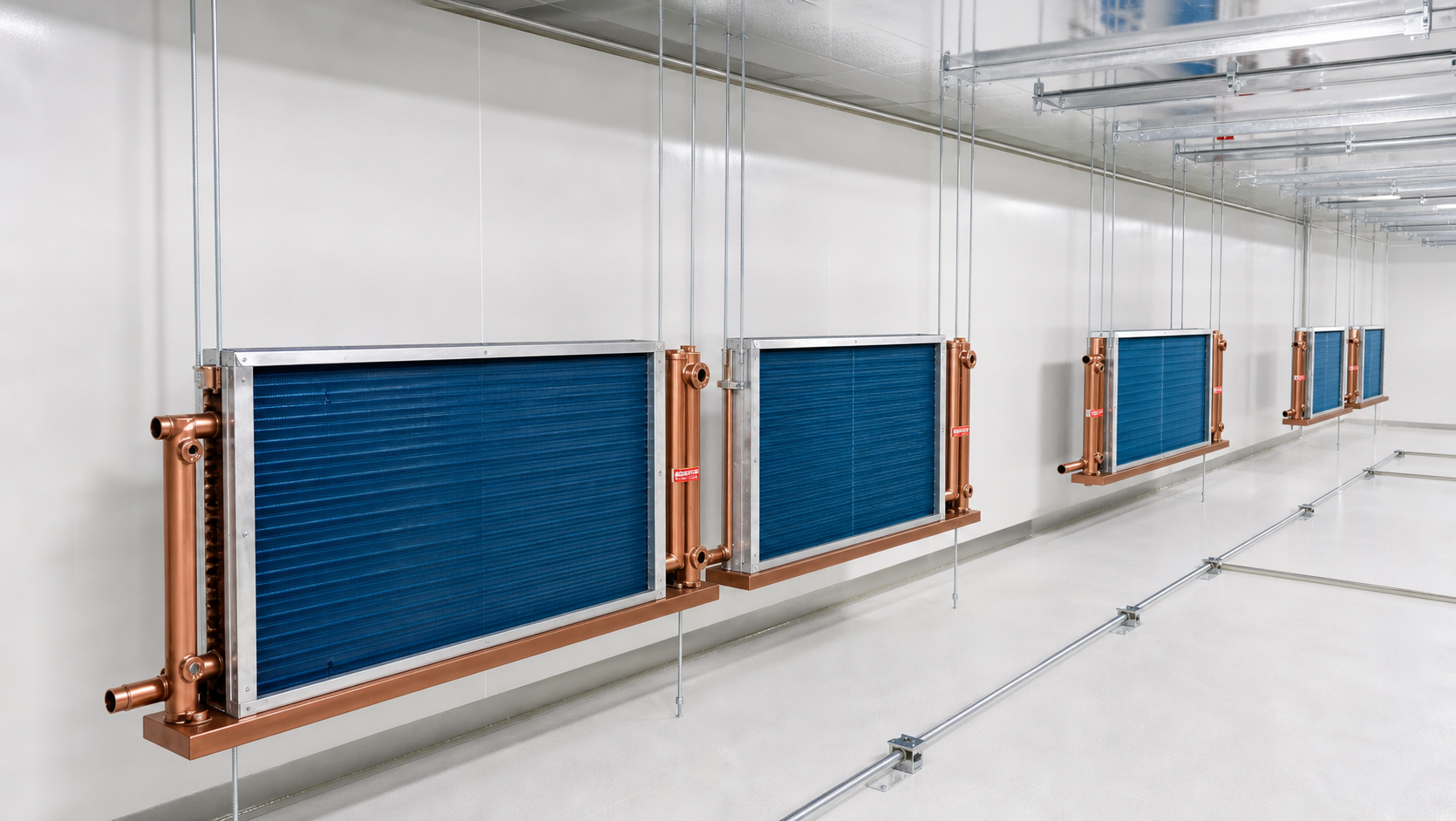
The no-condensation design approach is what enables the energy savings in the first place. Once you see how it works, it’s obvious: A traditional heat exchanger performing both cooling and dehumidification needs to cool air below the dew point and then reheat it to get to the desired temperature – an unnecessary energy penalty both at the start and the end of the process. Since a DCC doesn’t overcool below the dew point to start, there’s no second heating step needed, and no “dehum duty.” On top of that, by not wetting the coil, it doesn’t lose any heat-transfer capability due to evaporation, nor does it accumulate the biofilm on wetted surfaces that causes corrosion on conventional wet-fin tube coils.
That margin is particularly critical in a 240+ air-changes-per-hour (ACPH) lithography bay. Given the huge amount of recirculation, an out-of-specification coil operating just a bit below its target design margin would lead to humidity excursions within minutes, not hours. Unlike a standard AHU retrofit where this can be tolerated as part of a normal operating range, our DCC specification methodology calculates for margin to the specified temperature/dew point conditions at maximum airflow rather than average load.
02. SENSITIVE STAGE TOLERANCE
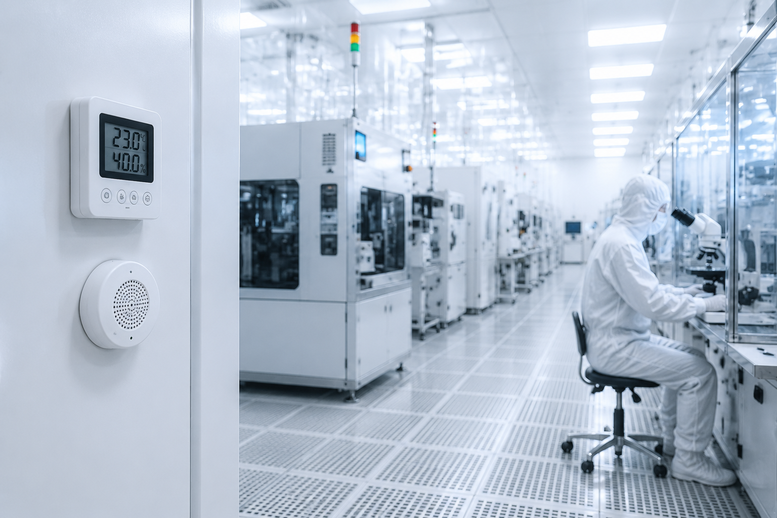
For the sensitive stages in a semiconductor process – typically in the photolithography or wafer-handling process bays – an industry design standard is a tight temperature control tolerance of ± 0.1 °C. A coupled cooling-dehumidification system struggles to meet these temperature demands while independently meeting the required dew point specification, because correcting for humidity on a shared coil automatically shifts the temperature too. Separating the two loops lets each one make an independent decision: if the room runs hot, the DCC adds cooling; if humidity climbs, the MAU adds moisture removal, without either correction disturbing the other.
Fluctuations in humidity also cause a buildup of static charge, which attracts particles and is itself a major threat to devices on the production floor of an ISO 5 photolithography bay. Decoupling not only saves energy, but it’s the only way to simultaneously maintain the stringent temperature tolerance and achieve a safe static-free humidity level, and the DDC controller is what ensures those two decisions are made separately. If your process has this kind of tight tolerance requirement, talk to our engineering team about your specific setpoint stability needs rather than assuming a standard coupled system will hold it.
“The number our DDC controller logic watches on every cleanroom retrofit quote is chilled-water supply temperature versus the room’s actual dew point, not just the nameplate cooling capacity — a coil that’s technically big enough can still condense if that 2-degree margin isn’t held through the whole distribution run.”
Coil Material Selection — Copper vs. 304/316L Stainless Steel
The DCC system remains dry, which eliminates the primary driver of corrosion in a conventional finned-tube coil – but “dry” isn’t the same as “non-corrosive.” Choosing among copper, 304 stainless or 316L stainless steel depends on your chilled water chemistry, the surrounding environment, and what your up-front and life-cycle costs are. Our Copper vs 304/316L Stainless Steel Decision Matrix below lays out that trade-off property by property.
Property
Copper (C11000/TP2)
304 / 316L Stainless
Thermal conductivity
~398 W/(m·K)
~15–16.3 W/(m·K)
Tensile strength (annealed)
~220–240 MPa
304: ~515–620 / 316L: ~485–620 MPa
Density (relative)
1.00 (8.96 g/cm³)
0.885 (7.93 g/cm³)
Standard electrode potential
+0.340 V (cathodic, relatively inert)
Passivated: approx. −0.05 to +0.10 V
Ammonia exposure
Not recommended — forms soluble complex, accelerates corrosion
Suitable
Chloride / coastal salt fog
Sensitive; needs insulated isolation from dissimilar metals
316L recommended (Mo content resists Cl⁻)
Fabrication speed (bending/forming)
High — soft, ductile, fast automated coiling
Low — work-hardens, needs annealing steps
Typical service life
15–20 years
20–25 years
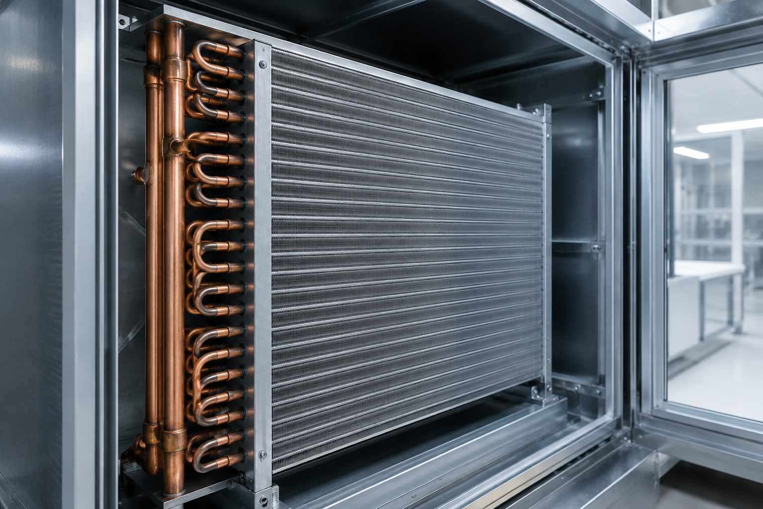
Copper remains the preferred material unless a corrosive element is a key consideration.
Here’s why the materials are different; copper thermal conductivity is approximately 24x that of stainless, but the dominant thermal resistance is in the airside boundary layer of a finned coil. Therefore the true heat-transfer difference between copper and stainless steel in a standard fin-and-tube coil, particularly plain-tube, is far less than that 24 figure implies. On an internally enhanced (microgrooved) coil, used in most standard cleanrooms today, copper’s convective benefit does come into play a bit more, and this explains why copper remains the preferred material unless a corrosive element is a key consideration.
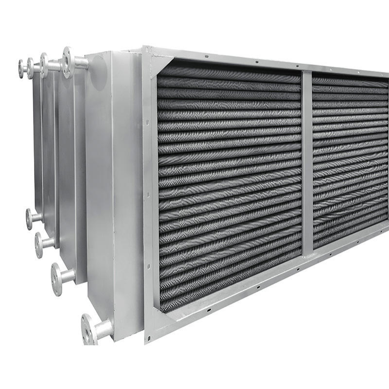
Ammonia, dissimilar metals, or coastal chlorides tip the balance to 316L stainless steel.
Where the balance tips towards stainless is in those rare instances where we deal with the truly exotic materials, ammonia being the deal-breaker for copper. Where we know process streams are releasing ammonia, which in turn readily creates copper-ammonia complex and corrosion. Those situations would call for a 316L stainless steel, irrespective of the up-front material cost. Another such instance is when the coil might be coming into contact with a dissimilar metal like galvanized steel supports or aluminum framework; this causes galvanic corrosion. At such junctions, we must incorporate some insulating means like PTFE/EPDM gasket material, or nylon sleeving on the coil tube OD and let this come to rest in the support or bracket.
For what’s after all simply a sensible cooling coil (not one that’s meant to get cold and sweat, which has its own distinct failure modes like stress-corrosion cracking due to chlorides) corrosion can be readily managed, with chloride stress corrosion being the equivalent stainless failure mode we must guard against (304 is susceptible to this, and if used in a coastal facility, or a facility where chlorinated cleaning chemicals are used, then we specify 316L over 304 for its higher molybdenum content, and field-welds at 450-850°C risk sensitization and must also be avoided). Larger tube diameter, thicker tube wall… these things can be chosen on an account of trying to make a stronger, more wear resistant tube that’s harder to corrode over the service life, perhaps a trade off of heat transfer for wear life.
Full Lifecycle Cost Pattern
Stainless costs less per pound (roughly one quarter to one fifth that of copper), but copper can be bent nearly at line speed, where the bend on a stainless coil runs at only about 15% of line speed and requires an annealing pass between bends to prevent cracking. For typical water quality, and not at the coast, copper wins because the labor and tooling are the primary drivers and stainless is simply more costly due to its difficulty in being manipulated. However in an environment with severe corrosion risk the potential benefits in less downtime for leaks and repairs may out weigh the added material and installation costs for a 20-25 year service life of a stainless steel coil. It’s truly a situation dependent issue.
Koven Air can engineer hybrid configurations when it makes sense, for example: a copper coil block built around heat transfer efficiency with 304/316L headers and connection piping for strong joints with resistance to corrosion at those points, where the copper-to-stainless connection is performed using silver brazing or a specialized TIG welding process, rather than directly connecting two different materials.
Engineering Reference Case — ISO 3 Semiconductor Fab Cleanroom Cooling Design.
To illustrate the MGR + EN + DCC architectural configuration at its peak operational challenge, let’s examine a real-world industrial case instead of a marketing brief. Below is a portion of an industry-documented engineering design case of a semiconductor cleanroom facility in the Pudong district of Shanghai. It’s presented here to offer the industry an example of how decoupled cleanroom cooling design is put into practice, not as a Koven Air project.
Facility scope
37,497.91 m² multi-level semiconductor fabrication and R&D building
Critical zone classification
ISO 3 (comparable to legacy FS209E Class 1)
System architecture
MAU (humidity/pressure) + DCC (sensible) + FFU (particulate)
MAU configuration
4 units, 95,000 CMH each, 3-duty/1-standby
DCC chilled water supply/return
Approx. 13–14°C / 18–20°C
DCC coil construction
Copper tube, hydrophilic aluminum fin, 2–4 rows
Airflow pattern
Top supply, bottom/side return; DCC in ceiling plenum
FFU coverage
100% in ISO 3 critical zone; 25–75% in supporting zones
Coordinating DCC commissioning and motorized valve strategy is critical for avoiding early damage.
It’s worth highlighting two aspects of this case which are commonly misunderstood during paper-based design. Firstly, the DCC is designated for sensible heat during operation, but during commissioning it was expected to momentarily assist with the latent load while the overall system came online in synchronized operation – highlighting the importance of coordinating the specification of the DCC with the sequencing of the MAU commissioning process. Secondly, the documented valve strategy placed motorized shut-off valves at both the MAU inlet and outlet: the inlet valve closes to keep outside air from damaging the coil bank when the unit is idle, while outlet-side protection is more commonly handled with a check valve than a second motorized valve, which represents a minor, but nevertheless real, trade-off between initial cost and design detail for discussion with your registered professional engineer.
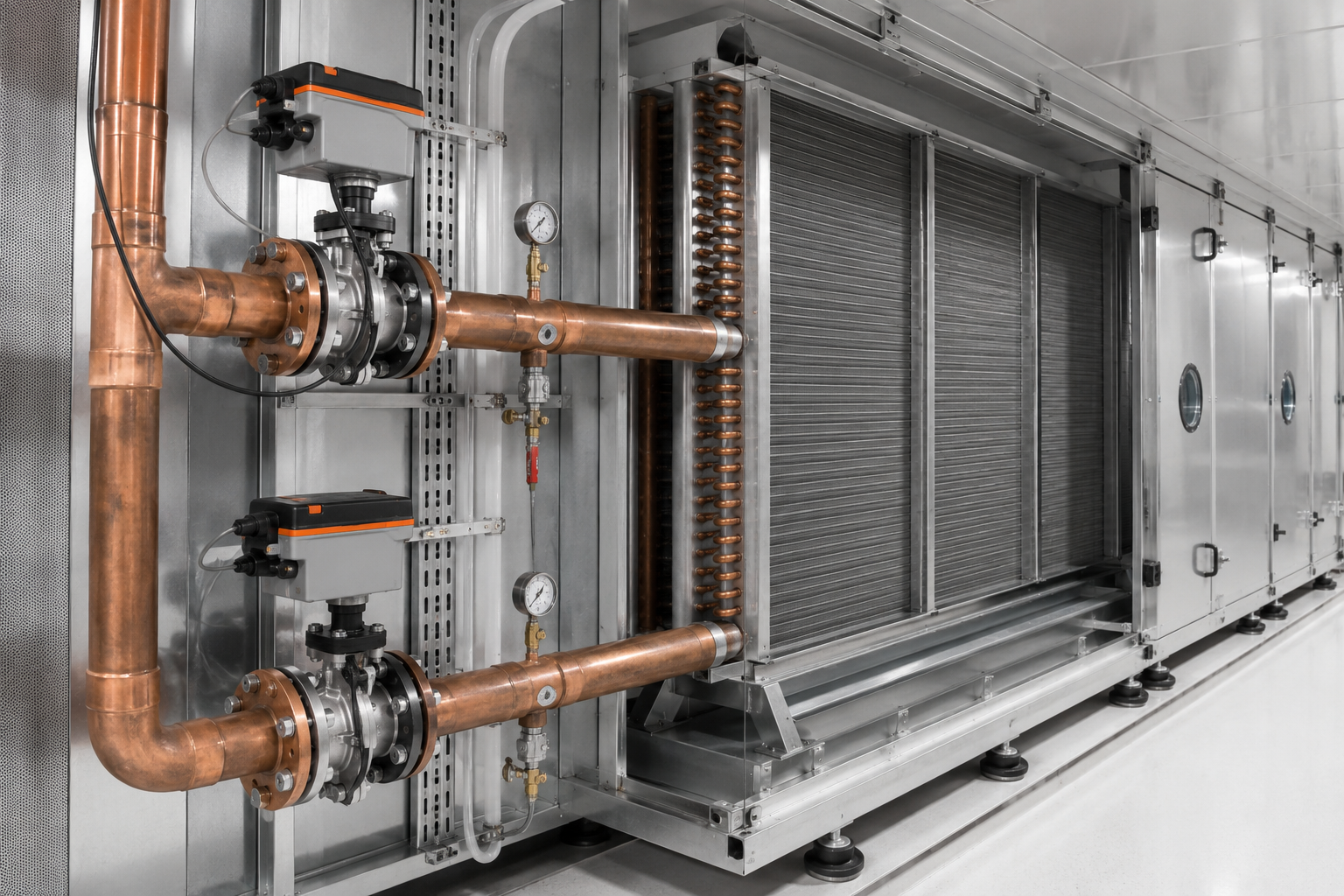
A 5-7°C supply-to-return differential indicates real-time thermal load irrespective of capacity.
As part of the building’s acceptance, a 5-7 degree C DCC supply to return differential temperature specification was used to indicate real time thermal load, a useful and practical metric for any DCC application irrespective of its capacity. Maintenance access for routine cleaning of fin surfaces and servicing of the water valves follows field practice: 100 mm to an adjacent coil bank, and an interior margin of 320 to 350 mm within the interior edge of the coil frame.
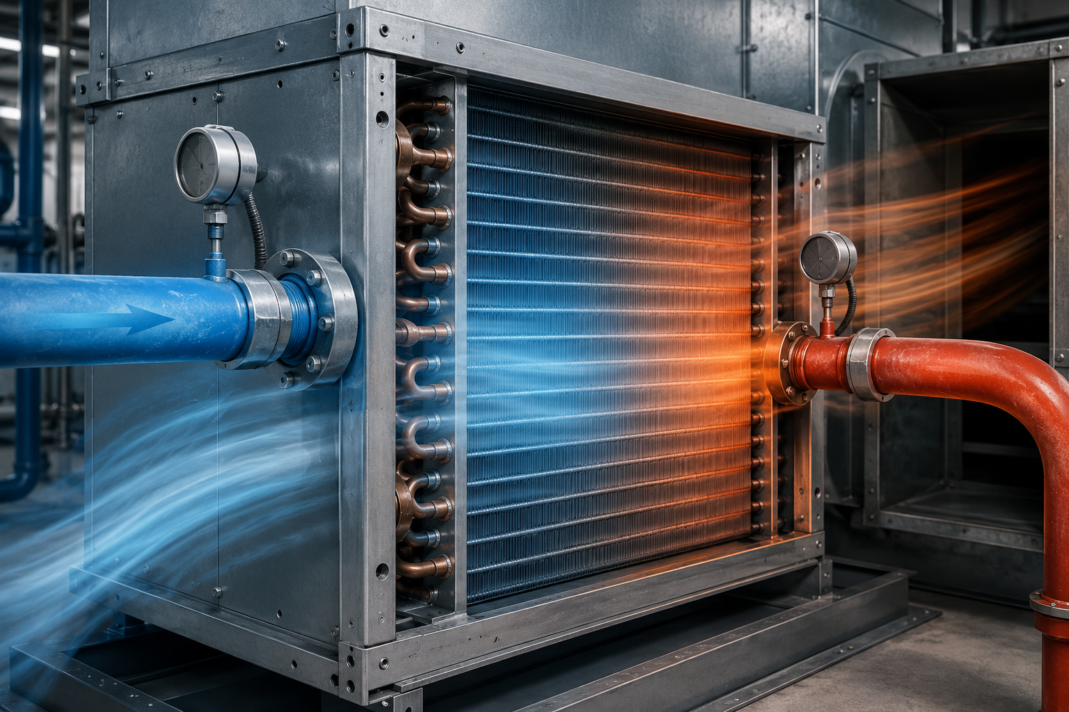
At Koven Air, our coils are designed specifically to target the same 5-7 degree C differential, which helps ensure performance doesn’t become part of the “tuning” at the time of commissioning.
Should you be in the planning stages of an equivalent cleanroom of ISO 3-5 purity, share your MAU/FFU layout and target ACH with our engineering team for a load calculation matched to your specific building, not a generalized reference case.
Design Standards & Filtration Alignment
ISO 14644 / EN 1822
PROC + EN. A common mistake in cleanroom audits is a coil that’s chosen to match a general ‘cleanroom rated’ designation instead of the actual classification and filter standard the auditor is reviewing – it’s this discrepancy that can cause problems and is costly to correct post-installation. Koven Air holds ISO 9001:2015 quality management certification and CE marking at the company level, and designs the cleanroom DCC product line to be in line with the classification and filtration standard the facility is currently being audited for, rather than some arbitrary specification that was invented in-house.
ISO 9001:2015
Koven Air quality management system
CE
Koven Air equipment certification
ISO 14644-1:2015
Air cleanliness classification
EN 1822
HEPA/ULPA filtration grading
ASME BPE-aligned
Hygienic construction reference (pharma-grade option)
316L option
CIP/SIP-compatible construction
Semiconductor vs. Pharma Protocols
If you are involved with semiconductor and general high-precision electronics cleanrooms, then the ISO 14644-1:2015 classification and EN 1822 filter standard are the only two that your DCC must be traceable against – and this is the premise upon which this page is built.

If, on the other hand, your application falls within the field of pharmaceutical manufacturing and requires 316L hygienic construction (via electropolishing to a controlled surface roughness value), EU GMP Annex 1 sanitary compliance, EHEDG compliant CIP/SIP performance, acid pickling and passivation, WFI critical zone compliance and full material traceability – you will require a materially different level of construction detail than for a standard semiconductor application.
Please refer to our Pharma Process Dry Coil product page if your application requires a GMP-specific cleanroom construction detail.
To be crystal clear and avoid the common ambiguity found in other marketing materials, this page specifically discusses the construction detail that addresses the classification and filtration standards listed. It is ISO 14644 and EN 1822 that define rooms and filter requirements; your coil merely needs to be compatible with the pressure, flow, and cleanliness requirements defined by the classification, and Koven Air is happy to supply supporting construction and material data for your facility’s own IQ/OQ documentation upon request.
Procurement Guide — Selection, Lead Time & After-Sales Support.
The vast majority of chilled water coil manufacturer catalogs base price off of cooling capacity alone. Cleanroom DCC pricing is different. It is based on a limited number of factors that directly apply to the unique conditions of your specific cleanroom, as the coil required for a semiconductor application at ISO 5 cleanliness is quite different from one built for an ISO 8 packaging anteroom.
Pricing Factors Framework
The main price drivers for a cleanroom DCC quotation are:
01
Material Construction: Copper, 304, or 316L stainless, and copper-coil / stainless-header designs.
02
Cooling Capacity & Face Area: Dictated by required air changes per hour and sensible heat load.
03
Row Count & Fin Spacing: Impacts pressure drop, heat transfer, and dust holding capacity.
04
Construction-Record Level: Commercial-grade vs. full material trace and hygienic finish docs.
05
Control Requirements: Koven Air supplied valve/actuator, or integration with facility’s existing DDC controls.
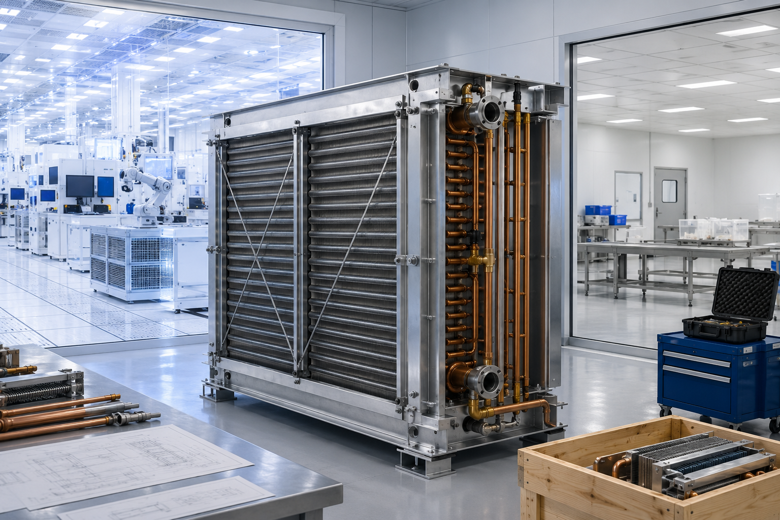
ENGINEERED ARCHITECTURE
Koven Air uses a 3-phase process to intercept errors before they manifest as change orders.
Our engineers professionally verify the parameters provided in your design based on the calculation method, rather than accepting a nameplate capacity order as a starting point – this prevents the problem of using generic HVAC rules of thumb for load calculations that are then incorporated into equipment manufacture.
Our technical team offer on-site support to install and commission equipment after it has been successfully manufactured and tested. Adjustments are made on-site as required by actual conditions -because a specified site condition and the as-built conditions are never identical.
We offer a lifetime of free technical service guidance with rapid responses to issues under the warranty period, plus ongoing training for engineers that will be maintaining the equipment long after commissioning.
Assess cross-border suppliers on financial stability, supply chain risk, and credible delivery records.
Evaluating any overseas HVAC equipment supplier
Apart from cost, chilled water coils suppliers and other cross-border equipment providers are assessed on the basis of financial stability, the level of risk it presents from a supply chain perspective, and whether it possesses a credible record of actually delivering and supporting the equipment it offer-not simply the capacity to manufacture it once. Any DCC provider, Koven Air included, can be asked for references from installation sites, details on their calculation methodologies and a clear procedure for handling technical issues after installation.
KOVEN AIR MFG.
ESTABLISHED:2007
EXPORT SINCE:2010
GLOBAL REACH:35+ COUNTRIES
The equipment produced by Koven Air is currently used in the commercial, industrial and specialized-control sector including for hospitals, manufacturing facilities for semiconductors and electronics, data centers and environments for growing crops-our process is applied with identical integrity regardless of size or specific use.
Cleanroom Engineering Tools & Calculators
Utilize our purpose-built sizing and selection utilities to accelerate your cleanroom HVACR design. These tools are engineered to help facility designers and MEP contractors quickly establish accurate baselines for decoupled sensible cooling operations.
Dewpoint Margin Calculator
Calculate the critical temperature margin required between your Chilled Water (CHW) supply and the room’s precise dewpoint to guarantee 100% sensible-only, non-condensing operation.
ISO Class Lookup
Cross-reference your target cleanroom ISO classification (ISO 5–8) against industry-standard Air Changes per Hour (ACH), airflow dynamics, and required terminal filtration mapping.
Material Selector
Evaluate operational tradeoffs between Copper (C11000) and Stainless Steel (304/316L) based on specific environmental corrosivity, fluid chemistry, and total lifecycle performance.
![Commercial Rooftop Unit Guide: Types, Sizing & Costs [2026]](https://kovenair.com/wp-content/uploads/2026/07/commercial-rooftop-unit-guide-featured-2-150x150.png)